


北京康拉德科技有限公司
张敏
手 机:
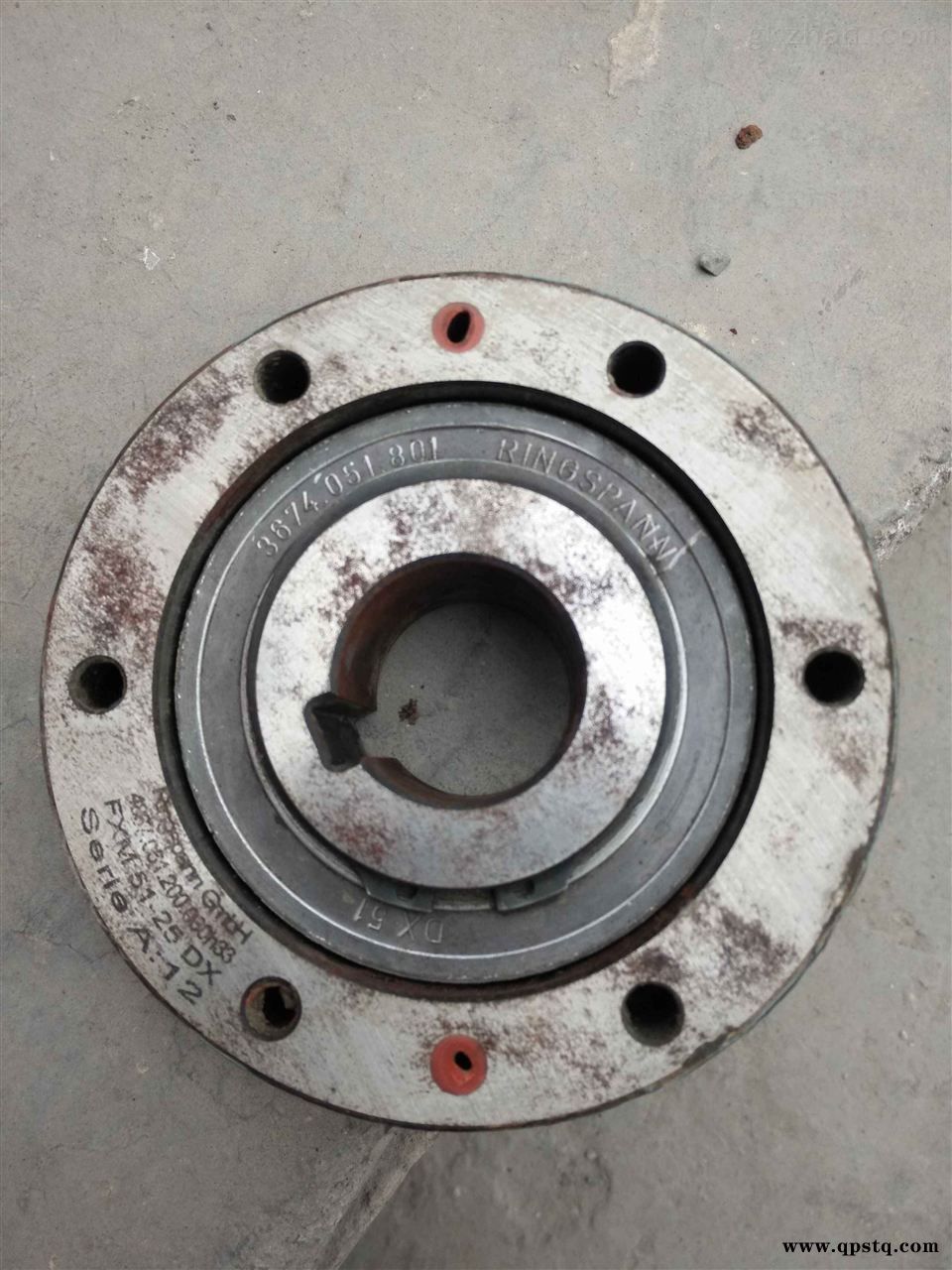
其他Ringspann 3674.051.801 FXM 51.25 DX for reducer M4PSF90 逆止器
+ BOX TYPE GEARHEAD
TERMINAL BOX TYPE MOTOR
3674.051.801 FXM 51.25 DX逆止器秒报价+ BOX TYPE GEARHEAD
Motor Specification
Lead Wire Type
8IDG(S)A-15G
8IDG(S)B-15G
8IDG(S)C-15G
8IDG(S)D-15G
8IDG(S)E-15G
8IDG(S)F-15G
8IDG(S)G-15G
8IDG(S)H-15G
8IDG(S)I-15G
8IDG(S)J-15G
8IDG(S)K-15G
8IDG(S)L-15G
8IDG(S)M-15G
8IDG(S)N-15G
8IDG(S)O-15G
1/50
Single Phase 110
Single Phase 115
其他Ringspann 3674.051.801 FXM 51.25 DX for reducer M4PSF90 逆止器Single Phase 220
Single Phase 220
Single Phase 230
Single Phase 230
Three Phase 220
Three Phase 220
Three Phase 230
Three Phase 230
Three Phase 380
Three Phase 380
Three Phase 400
Three Phase 440
Three Phase 440
60
60
50
60
3674.051.801 FXM 51.25 DX逆止器秒报价50
60
50
60
50
60
50
60
50
50
60
0.4 650 65 9.2 950 95 13.48 1550 3.5 250
其他Ringspann 3674.051.801 FXM 51.25 DX for reducer M4PSF90 逆止器1300 130 18.5
1300 130 18.5
1300 130 18.5
700 70 9.9 1120 112 15.9 1300
650 65 9.2 1000 100 14.2 1550
750 75 10.6 1120 112 15.9 1300
650 65 9.2 1000 100 14.2 1550
1200 120 17 1300
1000 100 14.2 1550
1200 120 17 1300
1000 100 14.2 1550
1200 120 17 1300
1000 100 14.2 1550
1200 120 17 1300
1000 100 14.2 1550
1000 100 14.2 1550
1.5 400
- -
0.25
0.25
0.14
0.11
Output
HP W VAC Hz A gfcm oz-in mN.m mN.m gfcm oz-in r/min VAC ?
Voltage Starting Torque Rated Torque Capacitor Rated
Speed Freq. Current
15
8IDG(S)A-15G-T
8IDG(S)B-15G-T
8IDG(S)C-15G-T
8IDG(S)D-15G-T
8IDG(S)E-15G-T
8IDG(S)F-15G-T
8IDG(S)G-15G-T
8IDG(S)H-15G-T
8IDG(S)i-15G-T
8IDG(S)J-15G-T
8IDG(S)K-15G-T
8IDG(S)L-15G-T
8IDG(S)M-15G-T
8IDG(S)N-15G-T
8IDG(S)O-15G-T
Terminal Box Type
Model
8IDGū-15G : Pinion Shaft Type
8IDSū-15 : Round Shaft Type
?Enter the gear ratio in the box (ū) within the model name. A colored background indicates gear shaft rotation in the same direction as the
motor shaft ; a white background indicates rotation in the opposite direction.
?The speed is calculated by dividing the motor's synchronous speed (50Hz : 1500 r/min, 60 Hz : 1800 r/min) by the gear ratio.
?The actual speed is 2~20% less than the displayed value, depending on the size of the load.
?If more slow speed is needed than above value, use decimal gearhead with a gear ratio of 10:1 could be used between general gearhead and
motor. Even in this case, just speed will be reduced without increase in permissible torque; the maximum permissible torque is 80kgfcm
(8N.m, 71lb-in).
Permissible Torque When using gearhead
TP
TP
TP
TP
TP
TP
TP
TP
TP
TP
TP
TP
TP
TP
TP
?Enter the ?Phase & Voltage?code in the box(ū) within the motor model name.
??Pinion Shaft?is for attaching gearhead and ?Round Shaft?is for using motor only.
: Contains a built-in thermal protector. If a motor overheats for any reason the thermal protector opened and the motor stops. When the
motor temperature drops, the thermal protector closes and the motor restarts. Be sure to turn the motor off before inspecting.
TP
DKM CO.,LTD. ?23?
Dimension
INDUCTION 15W
* Note?Above table indicates output shaft dimension made by user?s
request and ? indicates the basic dimension in factory shipping.
? The direction of motor rotation is as viewed from the shaft end of the motor.
? CW represents the clockwise direction, while CCW represents the counterclockwise direction.
? Connection diagrams are also valid for the equivalent round shaft type.
? Change the direction of single-phase motor rotation only after bringing the motor to a stop. If an attempt is made to change the direction of
rotation while the motor is rotating, the motor may ignore the reversing command or change its direction after some delay.
Not Available
Connection Diagrams
Single phase (CW, CCW) Three phase (CW, CCW)
CW?To rotate the motor in a clockwise(CW)
direction, flip switch SW to CW.
CCW?To rotate it in a countercloc kwise (CCW)
direction, flip switch SW to CCW.
?24? DKM CO.,LTD.
ū80mm(3.15in.)
INDUCTION MOTOR
25W
LEAD WIRE TYPE MOTOR
+ BOX TYPE GEARHEAD
TERMINAL BOX TYPE MOTOR
+ BOX TYPE GEARHEAD
?Enter the gear ratio in the box (ū) within the model name. A colored background indicates gear shaft rotation in the same direction as the
motor shaft ; a white background indicates rotation in the opposite direction.
?The speed is calculated by dividing the motor's synchronous speed (50Hz : 1500 r/min, 60 Hz : 1800 r/min) by the gear ratio.
?The actual speed is 2~20% less than the displayed value, depending on the size of the load.
?If more slow speed is needed than above value, use decimal gearhead with a gear ratio of 10:1 could be used between general gearhead and
motor. Even in this case, just speed will be reduced without increase in permissible torque; the maximum permissible torque is 80kgfcm
(8N.m, 71lb-in).
Permissible Torque When using gearhead
Motor Specification
?Enter the ?Phase & Voltage?code in the box(ū) within the motor model name.
??Pinion Shaft?is for attaching gearhead and ?Round Shaft?is for using motor only.
: Contains a built-in thermal protector. If a motor overheats for any reason the thermal protector opened and the motor stops. When the
motor temperature drops, the thermal protector closes and the motor restarts. Be sure to turn the motor off before inspecting.
TP
Lead Wire Type
8IDG(S)A-25G
8IDG(S)B-25G
8IDG(S)C-25G
8IDG(S)D-25G
8IDG(S)E-25G
8IDG(S)F-25G
8IDG(S)G-25G
8IDG(S)H-25G
8IDG(S)I-25G
8IDG(S)J-25G
8IDG(S)K-25G
8IDG(S)L-25G
8IDG(S)M-25G
8IDG(S)N-25G
8IDG(S)O-25G
8IDG(S)A-25G-T
8IDG(S)B-25G-T
8IDG(S)C-25G-T
8IDG(S)D-25G-T
8IDG(S)E-25G-T
8IDG(S)F-25G-T
8IDG(S)G-25G-T
8IDG(S)H-25G-T
8IDG(S)I-25G-T
8IDG(S)J-25G-T
8IDG(S)K-25G-T
8IDG(S)L-25G-T
8IDG(S)M-25G-T
8IDG(S)N-25G-T
8IDG(S)O-25G-T
1/30
Single Phase 110
Single Phase 115
Single Phase 220
Single Phase 220
Single Phase 230
Single Phase 230
Three phase 220
Three phase 220
Three phase 230
Three phase 230
Three phase 380
Three phase 380
Three phase 400
Three phase 440
Three phase 440
60
60
50
60
50
60
50
60
50
60
50
60
50
50
60
0.6 1100 110 16 1600 160 23 1550 6.0 250
2.0 400
- -
- -
- -
1000 100 14
1900 190 27 1300
1600 160 23 1550
1900 190 27 1300
1600 160 23 1550
1500 150 21
1500 150 21
1800 180 25 1300
1500 150 21 1550
1800 180 25 1300
1500 150 21 1550
1800 180 25 1300
1500 150 21 1550
1500 150 21
1800 180 25 1300
1800 180 25 1300
1500 150 21 1550
0.3
0.25
0.14
0.11
Output
HP W VAC Hz A gfcm oz-in mN.m mN.m gfcm oz-in r/min VAC ?
Voltage Starting Torque Rated Torque Capacitor Rated
Speed Freq. Current
25
Terminal Box Type
Model
8IDGū-25G : Pinion Shaft Type
8IDSū-25 : Round Shaft Type
TP
TP
TP
TP
TP
TP
TP
TP
TP
TP
TP
TP
TP
TP
TP
60Hz
600 500 360 300 240 200 144 120 100 72 60 50 45 36 30 24 20 18 15 12
3 3.6 5 6 7.5 9 12.5 15 18 25 30 36 40 50 60 75 90 100 120 150
4.4 5.2 7.3 8.7 10.9 13.1 18.2 21.9 26.2 32.9 39.4 47.3 52.6 59.4 71.3 80 80 80 80 80
0.44 0.52 0.73 0.87 1.09 1.31 1.82 2.19 2.62 3.29 3.9 4.7 5.2 5.9 7.1 8 8 8 8 8
3.9 4.6 6.4 7.7 9.6 12 16 19 23 29 35 42 46 52 63 71 71 71 71 71
10 7 6 5
180 250 300 360
80 80 80 80
8 8 8 8
71 71 71 71
8IDGū-25G 8GBKūBMH
speed RPM (r/min)
Gear Ratio
Model
Motor/Gearhead
kgf cm
N.m
lb-in
50Hz
500 417 300 250 200 167 120 100 83 60 50 42 38 30 25 20 17 15 13 10
3 3.6 5 6 7.5 9 12.5 15 18 25 30 36 40 50 60 75 90 100 120 150
5.3 6.4 8.9 10.7 13.4 16.0 22.3 26.7 32.1 40.2 48.2 57.8 64.2 72.6 80 80 80 80 80 80
0.53 0.64 0.89 1.07 1.34 1.60 2.23 2.67 3.21 4.02 4.8 5.8 6.4 7.3 8 8 8 8 8 8
4.7 5.7 7.9 9.4 11.8 14 20 24 28 35 43 51 57 64 71 71 71 71 71 71
8 6 5 5
180 250 300 360
80 80 80 80
8 8 8 8
71 71 71 71
8IDGū-25G 8GBKūBMH
speed RPM (r/min)
Gear Ratio
Model
Motor/Gearhead
kgf cm
N.m
lb-in
DKM CO.,LTD. ?25?
Dimension
* Note?Above table indicates output shaft dimension made by user?s
request and ? indicates the basic dimension in factory shipping.
INDUCTION 25W
Connection Diagrams
Single phase (CW, CCW) Three phase (CW, CCW)
CW?To rotate the motor in a clockwise(CW)
direction, flip switch SW to CW.
CCW?To rotate it in a countercloc kwise (CCW)
direction, flip switch SW to CCW.
CCW?To change the rotation direction, change
any connections between U,V and W.
? The direction of motor rotation is as viewed from the shaft end of the motor.
? CW represents the clockwise direction, while CCW represents the counterclockwise direction.
? Connection diagrams are also valid for the equivalent round shaft type.
? Change the direction of single-phase motor rotation only after bringing the motor to a stop. If an attempt is made to change the direction of
rotation while the motor is rotating, the motor may ignore the reversing command or change its direction after some delay.
?26? DKM CO.,LTD.
ū90mm(3.54in.)
INDUCTION MOTOR
40W
LEAD WIRE TYPE MOTOR
+ BOX TYPE GEARHEAD
TERMINAL BOX TYPE MOTOR
+ BOX TYPE GEARHEAD
? Enter the gear ratio in the box (ū) within the model name. A colored background indicates gear shaft rotation in the same direction as the
motor shaft ; a white background indicates rotation in the opposite direction.
?The speed is calculated by dividing the motor's synchronous speed (50Hz : 1500 r/min, 60 Hz : 1800 r/min) by the gear ratio.
?If more slow speed is needed than above value, use decimal gearhead with a gear ratio of 10:1 could be used between general gearhead and
motor. Even in this case, just speed will be reduced without increase in permissible torque; the maximum permissible torque is 100kgfcm
(10N.m, 88lb-in).
Permissible Torque When using gearhead
Motor Specification
?Enter the ?Phase & Voltage?code in the box(ū) within the motor model name.
??Pinion Shaft?is for attaching gearhead and ?D-Cut Shaft?is for using motor only.
: Contains a built-in thermal protector. If a motor overheats for any reason the thermal protector opened and the motor stops. When the
motor temperature drops, the thermal protector closes and the motor restarts. Be sure to turn the motor off before inspecting.
TP
Lead Wire Type
9IDG(D)A-40G
9IDG(D)B-40G
9IDG(D)C-40G
9IDG(D)D-40G
9IDG(D)E-40G
9IDG(D)F-40G
9IDG(D)G-40G
9IDG(D)H-40G
9IDG(D)I-40G
9IDG(D)J-40G
9IDG(D)K-40G
9IDG(D)L-40G
9IDG(D)M-40G
9IDG(D)N-40G
9IDG(D)O-40G
9IDG(D)A-40G-T
9IDG(D)B-40G-T
9IDG(D)C-40G-T
9IDG(D)D-40G-T
9IDG(D)E-40G-T
9IDG(D)F-40G-T
9IDG(D)G-40G-T
9IDG(D)H-40G-T
9IDG(D)I-40G-T
9IDG(D)J-40G-T
9IDG(D)K-40G-T
9IDG(D)L-40G-T
9IDG(D)M-40G-T
9IDG(D)N-40G-T
9IDG(D)O-40G-T
1/15
Single Phase 110
Single Phase 115
Single Phase 220
Single Phase 220
Single Phase 230
Single Phase 230
Three phase 220
Three phase 220
Three phase 230
Three phase 230
Three phase 380
Three phase 380
Three phase 400
Three phase 440
Three phase 440
60
60
50
60
50
60
50
60
50
60
50
60
50
50
60
0.9 2000 200 28 2600 260 37 1550 10 250
2.5 400
- -
- -
- -
2000 200 28
3000 300 42 1300
2600 260 37 1550
3000 300 42 1300
2600 260 37 1550
2600 260 37
2600 260 37
3000 300 42 1300
2600 260 37 1550
3000 300 42 1300
2600 260 37 1550
3000 300 42 1300
2600 260 37 1550
2600 260 37
3000 300 42 1300
3000 300 42 1300
2600 260 37 1550
0.45
0.4
0.22
0.18
Output
HP W VAC Hz A gfcm oz-in mN.m mN.m gfcm oz-in r/min VAC ?
Voltage Starting Torque Rated Torque Capacitor Rated
Speed Freq. Current
40
Terminal Box Type
Model
9IDGū-40G : Pinion Shaft Type
9IDDū-40 : D-Cut Shaft Type
TP
TP
TP
TP
TP
TP
TP
TP
TP
TP
TP
TP
TP
TP
TP
60Hz
900 600 500 360 300 240 200 180 144 120 100 72 60 50 45 36 30 24 20 18
2 3 3.6 5 6 7.5 9 10 12.5 15 18 25 30 36 40 50 60 75 90 100
5.0 6.8 8.2 11.3 13.6 17.0 20.4 22.7 28.4 34.0 40.8 51.1 61.3 73.6 81.5 100 100 100 100 100
0.50 0.68 0.82 1.13 1.36 1.70 2.04 2.27 2.84 3.40 4.08 5.11 6.1 7.4 8.2 10 10 10 10 10
4.4 6.0 7.2 10.0 12.0 15.0 18.0 20.0 25.1 30.0 36.0 45.1 54.1 65.0 72.0 88 88 88 88 88
15 12 10
120 150 180
100 100 100
10 10 10
88 88 88
9IDGū-40G 9GBKūMH
speed RPM (r/min)
Gear Ratio
Model
Motor/Gearhead
kgf cm
N.m
lb-in
50Hz
750 500 417 300 250 200 167 150 120 100 83 60 50 42 38 30 25 20 17 15
2 3 3.6 5 6 7.5 9 10 12.5 15 18 25 30 36 40 50 60 75 90 100
6.0 8.3 9.9 13.8 16.5 20.7 24.8 27.5 34.4 41.3 49.6 62.1 74.5 89.4 99.1 100 100 100 100 100
0.60 0.83 0.99 1.38 1.65 2.07 2.48 2.75 3.44 4.13 4.96 6.21 7.5 8.9 9.9 10 10 10 10 10
5.3 7.3 8.7 12.2 14.6 18.3 21.9 24.3 30.4 36.5 43.8 54.8 65.8 78.9 87.5 88 88 88 88 88
13 10 8
120 150 180
100 100 100
10 10 10
88 88 88
9IDGū-40G 9GBKūMH
speed RPM (r/min)
Gear Ratio
Model
Motor/Gearhead
kgf cm
N.m
lb-in
DKM CO.,LTD. ?27?
Dimension
* Note?Above table indicates output shaft dimension made by user?s
request and ? indicates the basic dimension in factory shipping.
INDUCTION 40W
Connection Diagrams
Single phase (CW, CCW) Three phase (CW, CCW)
CW?To rotate the motor in a clockwise(CW)
direction, flip switch SW to CW.
CCW?To rotate it in a countercloc kwise (CCW)
direction, flip switch SW to CCW.
CCW?To change the rotation direction, change
any connections between U,V and W.
? The direction of motor rotation is as viewed from the shaft end of the motor.
? CW represents the clockwise direction, while CCW represents the counterclockwise direction.
? Connection diagrams are also valid for the equivalent round shaft type.
? Change the direction of single-phase motor rotation only after bringing the motor to a stop. If an attempt is made to change the direction of
rotation while the motor is rotating, the motor may ignore the reversing command or change its direction after some delay.
?28? DKM CO.,LTD.
ū90mm(3.54in.)
INDUCTION MOTOR
60W
LEAD WIRE TYPE MOTOR
+ PB TYPE GEARHEAD
LEAD WIRE TYPE MOTOR
+ PF TYPE GEARHEAD
TERMINAL BOX TYPE MOTOR
+ PF TYPE GEARHEAD
?Enter the gear ratio in the box (ū) within the model name. A colored background indicates gear shaft rotation in the same direction as the
motor shaft ; a white background indicates rotation in the opposite direction.
?The speed is calculated by dividing the motor's synchronous speed (50Hz : 1500 r/min, 60 Hz : 1800 r/min) by the gear ratio.
?The actual speed is 2~20% less than the displayed value, depending on the size of the load.
?If more slow speed is needed than above value, use decimal gearhead with a gear ratio of 10:1 could be used between general gearhead and
motor. Even in this case, just speed will be reduced without increase in permissible torque; the maximum permissible torque is 200kgfcm
(20N.m, 177lb-in).
Permissible Torque When using gearhead
Motor Specification
?Enter the ?Phase & Voltage?code in the box(ū) within the motor model name.
??Pinion Shaft?is for attaching gearhead and ?D-Cut Shaft?is for using motor only.
: Contains a built-in thermal protector. If a motor overheats for any reason the thermal protector opened and the motor stops. When the
motor temperature drops, the thermal protector closes and the motor restarts. Be sure to turn the motor off before inspecting.
TP
Lead Wire Type
9IDG(D)A-60FP
9IDG(D)B-60FP
9IDG(D)C-60FP
9IDG(D)D-60FP
9IDG(D)E-60FP
9IDG(D)F-60FP
9IDG(D)G-60FP
9IDG(D)H-60FP
9IDG(D)I-60FP
9IDG(D)J-60FP
9IDG(D)K-60FP
9IDG(D)L-60FP
9IDG(D)M-60FP
9IDG(D)N-60FP
9IDG(D)O-60FP
9IDG(D)A-60FP-T
9IDG(D)B-60FP-T
9IDG(D)C-60FP-T
9IDG(D)D-60FP-T
9IDG(D)E-60FP-T
9IDG(D)F-60FP-T
9IDG(D)G-60FP-T
9IDG(D)H-60FP-T
9IDG(D)I-60FP-T
9IDG(D)J-60FP-T
9IDG(D)K-60FP-T
9IDG(D)L-60FP-T
9IDG(D)M-60FP-T
9IDG(D)N-60FP-T
9IDG(D)O-60FP-T
1/12
Single Phase 110
Single Phase 115
Single Phase 220
Single Phase 220
Single Phase 230
Single Phase 230
Three phase 220
Three phase 220
Three phase 230
Three phase 230
Three phase 380
Three phase 380
Three phase 400
Three phase 440
Three phase 440
60
60
50
60
50
60
50
60
50
60
50
60
50
50
60
1.20 3000 300 42 3800 380 54 1550 16 250
4.0 400
- -
- -
- -
3000 300 42
4560 456 65 1300
3800 380 54 1550
4560 456 65 1300
3800 380 54 1550
5000 500 71
5000 500 71
4560 456 65 1300
3800 380 54 1550
4560 456 65 1300
3800 380 54 1550
4560 456 65 1300
3800 380 54 1550
5000 500 71
4560 456 65 1300
4560 456 65 1300
3800 380 54 1550
0.60
0.60
0.38
0.27
Output
HP W VAC Hz A gfcm oz-in mN.m mN.m gfcm oz-in r/min VAC ?
Voltage Starting Torque Rated Torque Capacitor Rated
Speed Freq. Current
60
Terminal Box Type
Model
9IDGū-60FP : Pinion Shaft Type
9IDDū-60F : D-Cut Shaft Type
TP
TP
TP
TP
TP
TP
TP
TP
TP
TP
TP
TP
TP
TP
TP
60Hz
900 600 500 360 300 240 200 144 120 100 90 72 60 50 45 36 30 24 20 18
2 3 3.6 5 6 7.5 9 12.5 15 18 20 25 30 36 40 50 60 75 90 100
7.5 9.7 11.7 16.2 19.4 24.3 29.2 36.5 43.8 52.6 59.0 66.0 79.2 95 106 132 158 177 200 200
0.8 1.0 1.2 1.6 1.9 2.4 2.9 3.7 4.4 5.3 5.9 6.6 7.9 9.5 10.6 13.2 15.8 17.7 20 20
6.6 8.6 10 14 17 21 26 32 39 46 52 58 70 84 94 117 140 156 177 177
15 12 10
120 150 180
200 200 200
20 20 20
177 177 177
9PBKūBH
9PFKūBH 9IDGū-60FP
speed RPM (r/min)
Gear Ratio
Model
Motor/Gearhead
kgf cm
N.m
lb-in
50Hz
750 500 417 300 250 200 167 120 100 83 75 60 50 42 38 30 25 20 17 15
2 3 3.6 5 6 7.5 9 12.5 15 18 20 25 30 36 40 50 60 75 90 100
10.0 12.2 14.6 20.3 24 30 37 46 55 66 72 83 99 119 132 165 198 200 200 200
1.0 1.2 1.5 2.0 2.4 3.0 3.7 4.6 5.5 6.6 7.2 8.3 9.9 11.9 13.2 16.5 20 20 20 20
8.8 10.8 12.9 17.9 21.5 26.8 32.2 40.3 48.4 58.0 63.6 72.8 87 105 117 146 175 177 177 177
13 10 8
120 150 180
200 200 200
20 20 20
177 177 177
9PBKūBH
9PFKūBH 9IDGū-60FP
speed RPM (r/min)
Gear Ratio
Model
Motor/Gearhead
kgf cm
N.m
lb-in
DKM CO.,LTD. ?29?
Dimension
INDUCTION 60W
* Note?Above table indicates output shaft dimension made by user?s
request and ? indicates the basic dimension in factory shipping.
Connection Diagrams
Single phase (CW, CCW) Three phase (CW, CCW)
CW?To rotate the motor in a
clockwise(CW) direction, flip
switch SW to CW.
CCW?To rotate it in a countercloc
kwise (CCW) direction, flip
switch SW to CCW.
CCW?To change the rotation direction, change
any connections between U,V and W.
? The direction of motor rotation is as viewed from the shaft end of the motor.
? CW represents the clockwise direction, while CCW represents the counterclockwise direction.
? Connection diagrams are also valid for the equivalent round shaft type.
? Change the direction of single-phase motor rotation only after bringing the motor to a stop. If an attempt is made to change the direction of
rotation while the motor is rotating, the motor may ignore the reversing command or change its direction after some delay.
?30? DKM CO.,LTD.
ū90mm(3.54in.)
90W
LEAD WIRE TYPE MOTOR
+ PB TYPE GEARHEAD
LEAD WIRE TYPE MOTOR
+ PF TYPE GEARHEAD
TERMINAL BOX TYPE MOTOR
+ PF TYPE GEARHEAD
LEAD WIRE TYPE MOTOR
+ HB TYPE GEARHEAD
Permissible Torque When using gearhead
Motor Specification
?Enter the gear ratio in the box (ū) within the gearhead model name. A colored background indicates gear shaft rotation in the same direction
as the motor shaft ; a white background indicates rotation in the opposite direction.
?The speed is calculated by dividing the motor?s synchronous speed (50Hz : 1500 r/min, 60 Hz : 1800 r/min) by the gear ratio.
?The actual speed is 2~20% less than the displayed value, depending on the size of the load.
?If more slow speed is needed than above value, use decimal gearhead with a gear ratio of 10:1 could be used between general gearhead and
motor. Even in this case, just speed will be reduced without increase in permissible torque; the maximum permissible torque is 200kgfcm
(P type) / 300kgfcm (H type).
INDUCTION MOTOR
?Enter the ?Phase & Voltage?code in the box(ū) within the motor model name.
??Pinion Shaft?is for attaching gearhead and ?D-Cut Shaft?is for using motor only.
: Contains a built-in thermal protector. If a motor overheats for any reason the thermal protector opened and the motor stops. When the
motor temperature drops, the thermal protector closes and the motor restarts. Be sure to turn the motor off before inspecting.
TP
TP
TP
TP
TP
TP
TP
TP
TP
TP
TP
TP
TP
TP
TP
TP
Lead Wire Type
9IDG(D)A-90FP(H)
9IDG(D)B-90FP(H)
9IDG(D)C-90FP(H)
9IDG(D)D-90FP(H)
9IDG(D)E-90FP(H)
9IDG(D)F-90FP(H)
9IDG(D)G-90FP(H)
9IDG(D)H-90FP(H)
9IDG(D)I-90FP(H)
9IDG(D)J-90FP(H)
9IDG(D)K-90FP(H)
9IDG(D)L-90FP(H)
9IDG(D)M-90FP(H)
9IDG(D)N-90FP(H)
9IDG(D)O-90FP(H)
9IDG(D)A-90FP(H)-T
9IDG(D)B-90FP(H)-T
9IDG(D)C-90FP(H)-T
9IDG(D)D-90FP(H)-T
9IDG(D)E-90FP(H)-T
9IDG(D)F-90FP(H)-T
9IDG(D)G-90FP(H)-T
9IDG(D)H-90FP(H)-T
9IDG(D)I-90FP(H)-T
9IDG(D)J-90FP(H)-T
9IDG(D)K-90FP(H)-T
9IDG(D)L-90FP(H)-T
9IDG(D)M-90FP(H)-T
9IDG(D)N-90FP(H)-T
9IDG(D)O-90FP(H)-T
1/8
Single Phase 110
Single Phase 115
Single Phase 220
Single Phase 220
Single Phase 230
Single Phase 230
Three phase 220
Three phase 220
Three phase 230
Three phase 230
Three phase 380
Three phase 380
Three phase 400
Three phase 440
Three phase 440
60
60
50
60
50
60
50
60
50
60
50
60
50
50
60
2.00 4500 450 64 5700 570 81 1550 20 250
5.0 400
- -
- -
- -
4500 450 64
6840 684 97 1300
5700 570 81 1550
6840 684 97 1300
5700 570 81 1550
7000 700 99
7000 700 99
6840 684 97 1300
5700 570 81 1550
6840 684 97 1300
5700 570 81 1550
6840 684 97 1300
5700 570 81 1550
7000 700 99
6840 684 97 1300
6840 684 97 1300
5700 570 81 1550
1.00
0.80
0.44
0.36
Output
HP W VAC Hz A gfcm oz-in mN.m mN.m gfcm oz-in r/min VAC ?
Voltage Starting Torque Rated Torque Capacitor Rated
Speed Freq. Current
90
Terminal Box Type
Model
9IDGū-90FP(H) : Pinion Shaft Type
9IDDū-90F : D-Cut Shaft Type
60Hz
900 600 500 360 300 240 200 144 120 100 90 72 60 50 45 36 30 24 20 18
2 3 3.6 5 6 7.5 9 12.5 15 18 20 25 30 36 40 50 60 75 90 100
12 14.6 17.5 24.3 29.2 36.5 43.7 54.8 65.7 78.8 88.0 99 119 143 158 198 200 200 200 200
1.2 1.5 1.8 2.4 2.9 3.7 4.4 5.5 6.6 7.9 8.8 9.9 12 14 16 20 20 20 20 20
10.6 12.9 15.5 21.5 25.8 32.2 38.6 48.4 58.0 69.6 77.7 87.4 105 126 140 175 177 177 177 177
15 12 10
120 150 180
200 200 200
20 20 20
177 177 177
198 232 259 300 300 300 300 300
20 23 26 30 30 30 30 30
175 205 229 265 265 265 265 265
- -- ------ -- -- --
9PBKūBH
9PFKūBH
9HBKūBH
9IDGū-90FP
9IDGū-90FH
speed RPM (r/min)
Gear Ratio
Model
Motor/Gearhead
kgf cm
N.m
lb-in
kgf cm
N.m
lb-in
50Hz
750 500 417 300 250 200 167 120 100 83 75 60 50 42 38 30 25 20 17 15
2 3 3.6 5 6 7.5 9 12.5 15 18 20 25 30 36 40 50 60 75 90 100
15 18.2 21.9 30.4 36.5 45.6 54.7 68.4 82.1 98.6 110 124 150 180 199 200 200 200 200 200
1.5 1.8 2.2 3.0 3.7 4.6 5.5 6.8 8.2 9.9 11 12 15 18 20 20 20 20 20 20
13.2 16.1 19.3 26.8 32.2 40.3 48.3 60 72 87 97 109 132 159 176 177 177 177 177 177
13 10 8
120 150 180
200 200 200
20 20 20
177 177 177
241 289 300 300 300 300 300 300
24 29 30 30 30 30 30 30
213 255 265 265 265 265 265 265
- -- ------ -- -- --
9PBKūBH
9PFKūBH
9HBKūBH
9IDGū-90FP
9IDGū-90FH
speed RPM (r/min)
Gear Ratio
Model
Motor/Gearhead
kgf cm
N.m
lb-in
kgf cm
N.m
lb-in
DKM CO.,LTD. ?31?
Dimension
* Note?Above table indicates output shaft dimension made by user?s
request and ? indicates the basic dimension in factory shipping.
INDUCTION 90W
?32? DKM CO.,LTD.
Connection Diagrams
Single phase (CW, CCW) Three phase (CW, CCW)
CW?To rotate the motor in a clockwise(CW)
direction, flip switch SW to CW.
CCW?To rotate it in a countercloc kwise (CCW)
direction, flip switch SW to CCW.
CCW?To change the rotation direction, change
any connections between U,V and W.
? The direction of motor rotation is as viewed from the shaft end of the motor.
? CW represents the clockwise direction, while CCW represents the counterclockwise direction.
? Connection diagrams are also valid for the equivalent round shaft type.
? Change the direction of single-phase motor rotation only after bringing the motor to a stop. If an attempt is made to change the direction of
rotation while the motor is rotating, the motor may ignore the reversing command or change its direction after some delay.
DKM CO.,LTD. ?33?
ū90mm(3.54in.)
INDUCTION MOTOR
120W
Motor Specification
Permissible Torque When using gearhead
?Enter the gear ratio in the box (ū) within the gearhead model name. A colored background indicates gear shaft rotation in the same direction
as the motor shaft ; a white background indicates rotation in the opposite direction.
?The speed is calculated by dividing the motor?s synchronous speed (50Hz : 1500 r/min, 60 Hz : 1800 r/min) by the gear ratio.
?The actual speed is 2~20% less than the displayed value, depending on the size of the load.
?If more slow speed is needed than above value, use decimal gearhead with a gear ratio of 10:1 could be used between general gearhead and
motor. Even in this case, just speed will be reduced without increase in permissible torque; the maximum permissible torque is 200kgfcm
(P type) / 300kgfcm (H type).
LEAD WIRE TYPE MOTOR
+ PB TYPE GEARHEAD
LEAD WIRE TYPE MOTOR
+ PF TYPE GEARHEAD
TERMINAL BOX TYPE MOTOR
+ PF TYPE GEARHEAD
LEAD WIRE TYPE MOTOR
+ HB TYPE GEARHEAD
?Enter the ?Phase & Voltage?code in the box(ū) within the motor model name.
??Pinion Shaft?is for attaching gearhead and ?D-Cut Shaft?is for using motor only.
: Contains a built-in thermal protector. If a motor overheats for any reason the thermal protector opened and the motor stops. When the
motor temperature drops, the thermal protector closes and the motor restarts. Be sure to turn the motor off before inspecting.
TP
Lead Wire Type
9IDG(D)A-120FP(H)
9IDG(D)B-120FP(H)
9IDG(D)C-120FP(H)
9IDG(D)D-120FP(H)
9IDG(D)E-120FP(H)
9IDG(D)F-120FP(H)
9IDG(D)G-120FP(H)
9IDG(D)H-120FP(H)
9IDG(D)I-120FP(H)
9IDG(D)J-120FP(H)
9IDG(D)K-120FP(H)
9IDG(D)L-120FP(H)
9IDG(D)M-120FP(H)
9IDG(D)N-120FP(H)
9IDG(D)O-120FP(H)
9IDG(D)A-120FP(H)-T
9IDG(D)B-120FP(H)-T
9IDG(D)C-120FP(H)-T
9IDG(D)D-120FP(H)-T
9IDG(D)E-120FP(H)-T
9IDG(D)F-120FP(H)-T
9IDG(D)G-120FP(H)-T
9IDG(D)H-120FP(H)-T
9IDG(D)I-120FP(H)-T
9IDG(D)J-120FP(H)-T
9IDG(D)K-120FP(H)-T
9IDG(D)L-120FP(H)-T
9IDG(D)M-120FP(H)-T
9IDG(D)N-120FP(H)-T
9IDG(D)O-120FP(H)-T
1/6
Single Phase 110
Single Phase 115
Single Phase 220
Single Phase 220
Single Phase 230
Single Phase 230
Three phase 220
Three phase 220
Three phase 230
Three phase 230
Three phase 380
Three phase 380
Three phase 400
Three phase 440
Three phase 440
60
60
50
60
50
60
50
60
50
60
50
60
50
50
60
2.50 5900 590 83 7600 760 108 1550 25 250
6 400
- -
- -
- -
5900 590 83
9100 910 129 1300
7600 760 108 1550
9100 910 129 1300
7600 760 108 1550
9300 930 132
9300 930 132
9100 910 129 1300
7600 760 108 1550
9100 910 129 1300
7600 760 108 1550
9100 910 129 1300
7600 760 108 1550
9300 930 132
9100 910 129 1300
9100 910 129 1300
7600 760 108 1550
1.20
1.00
0.55
0.54
Output
HP W VAC Hz A gfcm oz-in mN.m mN.m gfcm oz-in r/min VAC ?
Voltage Starting Torque Rated Torque Capacitor Rated
Speed Freq. Current
120
Terminal Box Type
Model
9IDGū-120FP(H) : Pinion Shaft Type
9IDDū-120F : D-Cut Shaft Type
TP
TP
TP
TP
TP
TP
TP
TP
TP
TP
TP
TP
TP
TP
TP
60Hz
900 600 500 360 300 240 200 144 120 100 90 72 60 50 45 36 30 24 20 18
2 3 3.6 5 6 7.5 9 12.5 15 18 20 25 30 36 40 50 60 75 90 100
17.5 18.7 22.5 31.2 37.4 46.8 56.1 70.2 84.2 101 114 126 152 182 200 200 200 200 200 200
1.8 1.9 2.3 3.1 3.7 4.7 5.6 7.0 8.4 10.1 11.4 12.6 15 18 20 20 20 20 20 20
15.5 16.5 19.9 27.5 33.2 41.3 49.5 62.0 74 89 101 111 134 161 177 177 177 177 177 177
15 12 10
120 150 180
200 200 200
20 20 20
177 177 177
220 240 300 300 300 300 300 300
22 24 30 30 30 30 30 30
194 212 265 265 265 265 265 265
- 20.6 24.8 - 41.1 - 61.7 77.2 93 111 - 139 167 200 -
- 2.1 2.5 - 4.1 - 6.2 7.7 9.3 11.1 - 13.9 16.7 20.0 -
- 18.2 21.9 - 36.3 - 54.5 68.2 81.8 98.1 - 122 148 177 -
9PBKūBH
9PFKūBH
9HBKūBH
9IDGū-120FP
9IDGū-120FH
speed RPM (r/min)
Gear Ratio
Model
Motor/Gearhead
kgf cm
N.m
lb-in
kgf cm
N.m
lb-in
50Hz
750 500 417 300 250 200 167 120 100 83 75 60 50 42 38 30 25 20 17 15
2 3 3.6 5 6 7.5 9 12.5 15 18 20 25 30 36 40 50 60 75 90 100
22.0 23.2 27.8 37.8 46.4 58.0 69.6 87.0 104 125 140 156 188 200 200 200 200 200 200 200
2.20 2.32 2.78 3.87 4.64 5.80 6.96 8.7 10.4 12.5 14.0 15.6 19 20 20 20 20 20 20 20
19.4 20.5 24.5 34.2 41.0 51.2 61.5 76.8 92 110 124 138 166 177 177 177 177 177 177 177
13 10 8
120 150 180
200 200 200
20 20 20
177 177 177
240 260 300 300 300 300 300 300
24 26 30 30 30 30 30 30
212 230 265 265 265 265 265 265
- 25.5 30.6 - 51.0 - 76.6 95.7 114 138 - 172 207 220 -
- 2.6 3.1 - 5.1 - 7.7 9.6 11.4 13.8 - 17.2 20.7 22 -
- 22.5 27.0 - 45.1 - 67.6 84.5 101 121 - 152 182 194 -
9PBKūBH
9PFKūBH
9HBKūBH
9IDGū-120FP
9IDGū-120FH
speed RPM (r/min)
Gear Ratio
Model
Motor/Gearhead
kgf cm
N.m
lb-in
kgf cm
N.m
lb-in
INDUCTION 120W
?34? DKM CO.,LTD.
Dimension
SHAFT
* Note?Above table indicates output shaft dimension made by user?s
request and ? indicates the basic dimension in factory shipping.
DKM CO.,LTD. ?35?
Connection Diagrams
Single phase (CW, CCW) Three phase (CW, CCW)
CW?To rotate the motor in a clockwise(CW)
direction, flip switch SW to CW.
CCW?To rotate it in a countercloc kwise (CCW)
direction, flip switch SW to CCW.
CCW?To change the rotation direction, change
any connections between U,V and W.
? The direction of motor rotation is as viewed from the shaft end of the motor.
? CW represents the clockwise direction, while CCW represents the counterclockwise direction.
? Connection diagrams are also valid for the equivalent round shaft type.
? Change the direction of single-phase motor rotation only after bringing the motor to a stop. If an attempt is made to change the direction of
rotation while the motor is rotating, the motor may ignore the reversing command or change its direction after some delay.
INDUCTION 120W
?36? DKM CO.,LTD.
ū90mm(3.54in.)
INDUCTION MOTOR
150W
Motor Specification
Permissible Torque When using gearhead
?Enter the gear ratio in the box (ū) within the gearhead model name. A colored background indicates gear shaft rotation in the same direction
as the motor shaft ; a white background indicates rotation in the opposite direction.
?The speed is calculated by dividing the motor?s synchronous speed (50Hz : 1500 r/min, 60 Hz : 1800 r/min) by the gear ratio.
?The actual speed is 2~20% less than the displayed value, depending on the size of the load.
?If more slow speed is needed than above value, use decimal gearhead with a gear ratio of 10:1 could be used between general gearhead and
motor. Even in this case, just speed will be reduced without increase in permissible torque; the maximum permissible torque is 200kgfcm (P
type) / 300kgfcm (H type).
LEAD WIRE TYPE MOTOR
+ PB TYPE GEARHEAD
LEAD WIRE TYPE MOTOR
+ PF TYPE GEARHEAD
TERMINAL BOX TYPE MOTOR
+ PF TYPE GEARHEAD
LEAD WIRE TYPE MOTOR
+ HB TYPE GEARHEAD
?Enter the ?Phase & Voltage?code in the box(ū) within the motor model name.
??Pinion Shaft?is for attaching gearhead and ?D-Cut Shaft?is for using motor only.
: Contains a built-in thermal protector. If a motor overheats for any reason the thermal protector opened and the motor stops. When the
motor temperature drops, the thermal protector closes and the motor restarts. Be sure to turn the motor off before inspecting.
TP
TP
TP
TP
TP
TP
TP
TP
TP
TP
Lead Wire Type
9IDG(D)G-150FP(H)
9IDG(D)H-150FP(H)
9IDG(D)I-150FP(H)
9IDG(D)J-150FP(H)
9IDG(D)K-150FP(H)
9IDG(D)L-150FP(H)
9IDG(D)M-150FP(H)
9IDG(D)N-150FP(H)
9IDG(D)O-150FP(H)
9IDG(D)G-150FP(H)-T
9IDG(D)H-150FP(H)-T
9IDG(D)I-150FP(H)-T
9IDG(D)J-150FP(H)-T
9IDG(D)K-150FP(H)-T
9IDG(D)L-150FP(H)-T
9IDG(D)M-150FP(H)-T
9IDG(D)N-150FP(H)-T
9IDG(D)O-150FP(H)-T
1/5
Three phase 220
Three phase 220
Three phase 230
Three phase 230
Three phase 380
Three phase 380
Three phase 400
Three phase 440
Three phase 440
50
60
50
60
50
60
50
50
60
1.02
11000 1100 156 1300
11400 1140 161
9300 930 132 1550 ? ? 11000 1100 156 1300
9300 930 132 1550
11400 1140 161
11000 1100 156 1300 ? ? 9300 930 132 1550
11000 1100 156 1300
11400 1140 161 11000 1100 156 1300 ? ?
9300 930 132 1550
0.66
0.54
Output
HP W VAC Hz A gfcm oz-in mN.m mN.m gfcm oz-in r/min VAC ?
Voltage Starting Torque Rated Torque Capacitor Rated
Speed Freq. Current
150
Terminal Box Type
Model
9IDGū-150FP(H) : Pinion Shaft Type
9IDDū-150F : D-Cut Shaft Type
60Hz
900 600 500 360 300 240 200 144 120 100 90 72 60 50 45 36 30 24 20 18
2 3 3.6 5 6 7.5 9 12.5 15 18 20 25 30 36 40 50 60 75 90 100
19 23.2 27.8 38.7 46.4 58.0 69.6 87 104 125 135 156 188 200 200 200 200 200 200 200
1.9 2.3 2.8 3.9 4.6 5.8 7.0 8.7 10.4 12.5 13.5 15.6 19 20 20 20 20 20 20 20
17 20 25 34 41 51 61 77 92 110 119 138 166 177 177 177 177 177 177 177
15 12 10
120 150 180
200 200 200
20 20 20
177 177 177
300 300 300 300 300 300 300 300
30 30 30 30 30 30 30 30
265 265 265 265 265 265 265 265
- 25.5 30.6 - 51.0 - 76.6 96 114 138 - 172 207 225 -
- 2.6 3.1 - 5.1 - 7.7 9.6 11.4 13.8 - 17.2 20.7 23 -
- 23 27 - 45 - 68 85 101 121 - 152 183 199 -
9PBKūBH
9PFKūBH
9HBKūBH
9IDGū-150FP
9IDGū-150FH
speed RPM (r/min)
Gear Ratio
Model
Motor/Gearhead
kgf cm
N.m
lb-in
kgf cm
N.m
lb-in
50Hz
750 500 417 300 250 200 167 120 100 83 75 60 50 42 38 30 25 20 17 15
2 3 3.6 5 6 7.5 9 12.5 15 18 20 25 30 36 40 50 60 75 90 100
24 29 34 48 58 72 86 108 129 155 167 193 200 200 200 200 200 200 200 200
2.4 2.9 3.4 4.8 5.8 7.2 8.6 10.8 12.9 15.5 16.7 19.3 20 20 20 20 20 20 20 20
21 25 30 42 51 64 76 95 114 137 148 171 177 177 177 177 177 177 177 177
13 10 8
120 150 180
200 200 200
20 20 20
177 177 177
300 300 300 300 300 300 300 300
30 30 30 30 30 30 30 30
265 265 265 265 265 265 265 265
- 31.6 37.9 - 63.3 - 94.9 119 142 171 - 213 220 250 -
- 3.2 3.8 - 6.3 - 9.5 11.9 14.2 17.1 - 21 22 25 -
- 28 33 - 56 - 84 105 125 151 - 188 194 221 -
9PBKūBH
9PFKūBH
9HBKūBH
9IDGū-150FP
9IDGū-150FH
speed RPM (r/min)
Gear Ratio
Model
Motor/Gearhead
kgf cm
N.m
lb-in
kgf cm
N.m
lb-in
DKM CO.,LTD. ?37?
Dimension
* Note?Above table indicates output shaft dimension made by user?s
request and ? indicates the basic dimension in factory shipping.
INDUCTION 150W
?38? DKM CO.,LTD.
Connection Diagrams
CCW?To change the rotation direction,
change any connections between
U,V and W.
? The direction of motor rotation is as viewed from the shaft end of the motor.
? CW represents the clockwise direction, while CCW represents the counterclockwise direction.
DKM CO.,LTD. ?39?
ū90mm(3.54in.)
INDUCTION MOTOR
180W
Permissible Torque When using gearhead
?Enter the gear ratio in the box (ū) within the gearhead model name. A colored background indicates gear shaft rotation in the same direction
as the motor shaft ; a white background indicates rotation in the opposite direction.
?The speed is calculated by dividing the motor?s synchronous speed (50Hz : 1500 r/min, 60 Hz : 1800 r/min) by the gear ratio.
?The actual speed is 2~20% less than the displayed value, depending on the size of the load.
?If more slow speed is needed than above value, use decimal gearhead with a gear ratio of 10:1 could be used between general gearhead and
motor. Even in this case, just speed will be reduced without increase in permissible torque; the maximum permissible torque is 200kgfcm (P
type) / 300kgfcm (H type).
Motor Specification
LEAD WIRE TYPE MOTOR
+ PB TYPE GEARHEAD
LEAD WIRE TYPE MOTOR
+ PF TYPE GEARHEAD
TERMINAL BOX TYPE MOTOR
+ PF TYPE GEARHEAD
LEAD WIRE TYPE MOTOR
+ HB TYPE GEARHEAD
?Enter the ?Phase & Voltage?code in the box(ū) within the motor model name.
??Pinion Shaft?is for attaching gearhead and ?D-Cut Shaft?is for using motor only.
: Contains a built-in thermal protector. If a motor overheats for any reason the thermal protector opened and the motor stops. When the
motor temperature drops, the thermal protector closes and the motor restarts. Be sure to turn the motor off before inspecting.
TP
TP
TP
TP
TP
Lead Wire Type
9IDG(D)C-180FP(H)
9IDG(D)D-180FP(H)
9IDG(D)E-180FP(H)
9IDG(D)F-180FP(H)
9IDG(D)C-180FP(H)-T
9IDG(D)D-180FP(H)-T
9IDG(D)E-180FP(H)-T
9IDG(D)F-180FP(H)-T
Single Phase 220
Single Phase 220
Single Phase 230
Single Phase 230
50
60
50
60
1.40
13500 1350 191 1300
7000 700 99
11300 1130 108 1550
6.5 400
13500 1350 191 1300
11300 1130 108 1550
Output
HP W VAC Hz A gfcm oz-in mN.m mN.m gfcm oz-in r/min VAC ?
Voltage Starting Torque Rated Torque Capacitor Rated
Speed Freq. Current
1/4 180
Terminal Box Type
Model
9IDGū-180FP(H) : Pinion Shaft Type
9IDDū-180F : D-Cut Shaft Type
60Hz
900 600 500 360 300 240 200 144 120 100 90 72 60 50 45 36 30 24 20 18
2 3 3.6 5 6 7.5 9 12.5 15 18 20 25 30 36 40 50 60 75 90 100
22 27 32 45 54 67 80 100 120 152 171 189 200 200 200 200 200 200 200 200
2.2 2.7 3.2 4.5 5.4 6.7 8.0 10 12 15 17 19 20 20 20 20 20 20 20 20
19 24 29 39 48 60 71 88 106 134 151 167 177 177 177 177 177 177 177 177
15 12 10
120 150 180
200 200 200
20 20 20
177 177 177
300 300 300 300 300 300 300 300
30 30 30 30 30 30 30 30
265 265 265 265 265 265 265 265
- 28 34 - 57 - 84 105 126 160 - 210 227 273 -
- 2.8 3.4 - 5.7 - 8.4 11 13 16 - 21 23 27 -
- 25 30 - 50 - 74 93 111 141 - 185 200 241 -
9PBKūBH
9PFKūBH
9HBKūBH
9IDG2-180FP
9IDG2-180FH
speed RPM (r/min)
Gear Ratio
Model
Motor/Gearhead
kgf cm
N.m
lb-in
kgf cm
N.m
lb-in
50Hz
750 500 417 300 250 200 167 120 100 83 75 60 50 42 38 30 25 20 17 15
2 3 3.6 5 6 7.5 9 12.5 15 18 20 25 30 36 40 50 60 75 90 100
25 32 39 54 65 81 97 122 145 200 200 200 200 200 200 200 200 200 200 200
2.5 3.2 3.9 5.4 6.5 8.1 9.7 12 15 19 20 20 20 20 20 20 20 20 20 20
22 29 34 48 57 71 86 107 128 168 177 177 177 177 177 177 177 177 177 177
13 10 8
120 150 180
200 200 200
20 20 20
177 177 177
300 300 300 300 300 300 300 300
30 30 30 30 30 30 30 30
265 265 265 265 265 265 265 265
- 34 41 - 68 - 105 128 153 200 - 230 287 300 -
- 3.4 4.1 - 6.8 - 10.5 13 15 20 - 23 28 30 -
- 30 36 - 60 - 90 113 135 177 - 203 245 265 -
9PBKūBH
9PFKūBH
9HBKūBH
9IDGC-180FP
9IDGC-180FH
speed RPM (r/min)
Gear Ratio
Model
Motor/Gearhead
kgf cm
N.m
lb-in
kgf cm
N.m
lb-in
INDUCTION 180W
?40? DKM CO.,LTD.
Dimension
* Note?Above table indicates output shaft dimension made by user?s
request and ? indicates the basic dimension in factory shipping.
DKM CO.,LTD. ?41?
? The direction of motor rotation is as viewed from the shaft end of the motor.
? CW represents the clockwise direction, while CCW represents the counterclockwise direction.
? Connection diagrams are also valid for the equivalent round shaft type.
? Change the direction of single-phase motor rotation only after bringing the motor to a stop. If an attempt is made to change the direction of
rotation while the motor is rotating, the motor may ignore the reversing command or change its direction after some delay.
Not Available
Connection Diagrams
Single phase (CW, CCW) Three phase (CW, CCW)
CW?To rotate the motor in a clockwise(CW)
direction, flip switch SW to CW.
CCW?To rotate it in a countercloc kwise (CCW)
direction, flip switch SW to CCW.
INDUCTION 180W
?42? DKM CO.,LTD.
ū90mm(3.54in.)
INDUCTION MOTOR
200W
Motor Specification
Permissible Torque When using gearhead
?Enter the gear ratio in the box (ū) within the gearhead model name. A colored background indicates gear shaft rotation in the same direction as the motor shaft
; a white background indicates rotation in the opposite direction.
?The speed is calculated by dividing the motor?s synchronous speed (50Hz : 1500 r/min, 60 Hz : 1800 r/min) by the gear ratio.
?The actual speed is 2~20% less than the displayed value, depending on the size of the load.
?If more slow speed is needed than above value, use decimal gearhead with a gear ratio of 10:1 could be used between general gearhead and motor. Even in
this case, just speed will be reduced without increase in permissible torque; the maximum permissible torque is 200kgfcm (P type) / 300kgfcm (H type).
LEAD WIRE TYPE MOTOR
+ PB TYPE GEARHEAD
LEAD WIRE TYPE MOTOR
+ PF TYPE GEARHEAD
TERMINAL BOX TYPE MOTOR
+ PF TYPE GEARHEAD
LEAD WIRE TYPE MOTOR
+ HB TYPE GEARHEAD
?Enter the ?Phase & Voltage?code in the box(ū) within the motor model name.
??Pinion Shaft?is for attaching gearhead and ?D-Cut Shaft?is ffor using motor only.
: Contains a built-in thermal protector. If a motor overheats for any reason the thermal protector opened and the motor stops. When the
motor temperature drops, the thermal protector closes and the motor restarts. Be sure to turn the motor off before inspecting.
TP
TP
TP
TP
TP
TP
TP
TP
TP
TP
Lead Wire Type
9IDG(D)G-200FP(H)
9IDG(D)H-200FP(H)
9IDG(D)I-200FP(H)
9IDG(D)J-200FP(H)
9IDG(D)K-200FP(H)
9IDG(D)L-200FP(H)
9IDG(D)M-200FP(H)
9IDG(D)N-200FP(H)
9IDG(D)O-200FP(H)
9IDG(D)G-200FP(H)-T
9IDG(D)H-200FP(H)-T
9IDG(D)I-200FP(H)-T
9IDG(D)J-200FP(H)-T
9IDG(D)K-200FP(H)-T
9IDG(D)L-200FP(H)-T
9IDG(D)M-200FP(H)-T
9IDG(D)N-200FP(H)-T
9IDG(D)O-200FP(H)-T
1/4
Three phase 220
Three phase 220
Three phase 230
Three phase 230
Three phase 380
Three phase 380
Three phase 400
Three phase 440
Three phase 440
50
60
50
60
50
60
50
50
60
1.60
15000 1500 212 1300
14500 1450 205
12500 1250 177 1550 ? ? 15000 1500 212 1300
12500 1250 177 1550
14500 1450 205
15000 1500 212 1300 ? ? 12500 1250 177 1550
15000 1500 212 1300
14500 1450 205 15000 1500 212 1300 ? ?
12500 1250 177 1550
0.90
0.68
Output
HP W VAC Hz A gfcm oz-in mN.m mN.m gfcm oz-in r/min VAC ?
Voltage Starting Torque Rated Torque Capacitor Rated
Speed Freq. Current
200
Terminal Box Type
Model
9IDGū-200FP(H) : Pinion Shaft Type
9IDDū-200F : D-Cut Shaft Type
60Hz
900 600 500 360 300 240 200 144 120 100 90 72 60 50 45 36 30 24 20 18
2 3 3.6 5 6 7.5 9 12.5 15 18 20 25 30 36 40 50 60 75 90 100
28 30 36 51 61 76 91 114 137 164 200 200 200 200 200 200 200 200 200 200
2.8 3 4 5 6 8 9 11 14 16 20 20 20 20 20 20 20 20 20 20
25 27 32 45 54 67 81 101 121 145 177 177 177 177 177 177 177 177 177 177
- 32 38.3 - 64 - 96 120 144 173 - 216 259 300 - 300 300 300 300 300
- 3 4 - 6 - 10 12 14 17 - 22 26 30 - 30 30 30 30 30
- 28 34 - 57 - 85 106 127 153 - 191 229 265 - 265 265 265 265 265
15 12 10
120 150 180
200 200 200
20 20 20
177 177 177
300 300 300
30 30 30
265 265 265
9PBKūBH
9PFKūBH
9HBKūBH
9IDGū-200FP
9IDGū-200FH
speed RPM (r/min)
Gear Ratio
Model
Motor/Gearhead
kgf cm
N.m
lb-in
kgf cm
N.m
lb-in
50Hz
750 500 417 300 250 200 167 120 100 83 75 60 50 42 38 30 25 20 17 15
2 3 3.6 5 6 7.5 9 12.5 15 18 20 25 30 36 40 50 60 75 90 100
33 37 45 62 74 92 111 139 166 200 200 200 200 200 200 200 200 200 200 200
3.3 4 4 6 7 9 11 14 17 20 20 20 20 20 20 20 20 20 20 20
29 33 39 54 65 82 98 122 147 176 177 177 177 177 177 177 177 177 177 177
- 39 47 - 78 - 117 146 175 210 - 262 300 300 - 300 300 300 300 300
- 4 5 - 8 - 12 15 18 21 - 26 30 30 - 30 30 30 30 30
- 34 42 - 69 - 103 129 155 185 - 231 265 265 - 265 265 265 265 265
13 10 8
120 150 180
200 200 200
20 20 20
177 177 177
300 300 300
30 30 30
265 265 265
9PBKūBH
9PFKūBH
9HBKūBH
9IDGū-200FP
9IDGū-200FH
speed RPM (r/min)
Gear Ratio
Model
Motor/Gearhead
kgf cm
N.m
lb-in
kgf cm
N.m
lb-in
DKM CO.,LTD. ?43?
Dimension
* Note?Above table indicates output shaft dimension made by user?s
request and ? indicates the basic dimension in factory shipping.
Connection Diagrams Please refer to page 38.
INDUCTION 200W
DKM CO.,LTD. ?45?
2 POLE MOTOR
2 POLE
INDEX
15W (ū80mm) 46
25W (ū80mm) 48
40W (ū90mm) 50
60W (ū90mm) 52
90W (ū90mm) 54
120W (ū90mm) 56
150W (ū90mm) 58
200W (ū90mm) 60
?46? DKM CO.,LTD.
ū80mm(3.12in.)
2 POLE MOTOR
15W
LEAD WIRE TYPE MOTOR TERMINAL BOX TYPE MOTOR
TP
TP
TP
TP
TP
TP
TP
TP
TP
TP
Motor Specification
Lead Wire Type
8IDSA-15-A
8IDSB-15-A
8IDSC-15-A
8IDSD-15-A
8IDSE-15-A
8IDSF-15-A
8IDSG-15-A
8IDSH-15-A
8IDSI-15-A
8IDSJ-15-A
8IDSA-15-A-T
8IDSB-15-A-T
8IDSC-15-A-T
8IDSD-15-A-T
8IDSE-15-A-T
8IDSF-15-A-T
8IDSG-15-A-T
8IDSH-15-A-T
8IDSI-15-A-T
8IDSJ-15-A-T
1/50
Single Phase 110
Single Phase 115
Single Phase 220
Single Phase 220
Single Phase 230
Single Phase 230
Three Phase 220
Three Phase 220
Three Phase 230
Three Phase 230
60
60
50
60
50
60
50
60
50
60
0.40 500 50 7 700 70 10 3200 6.0 250
2.0 400
?
500 50 7
600 60 8.5
840 84 72 2600
700 70 10 3200
840 84 12 2600
700 70 10 3200
2600
700 70 10 3200
2600
3200
0.25
0.25
Output
HP W VAC Hz A gfcm mN.m oz-in gfcm mN.m oz-in r/min VAC ?
Voltage Starting Torque Rated Torque Capacitor Rated
Speed Freq. Current
15
Terminal Box Type
Model
8IDSū-15-A : Round Shaft Type
?Enter the ?Phase & Voltage?code in the box(ū) within the motor model name.
??Round Shaft?is for using motor only.
: Contains a built-in thermal protector. If a motor overheats for any reason the thermal protector opened and the motor stops. When the
motor temperature drops, the thermal protector closes and the motor restarts. Be sure to turn the motor off before inspecting.
TP
DKM CO.,LTD. ?47?
2 POLE 15W
Connection Diagrams Please refer to page 53.
Dimension
P.C.D 94
* Note?Above table indicates output shaft
dimension made by user?s
request and ? indicates the basic
dimension in factory shipping.
?48? DKM CO.,LTD.
ū80mm(3.12in.)
2 POLE MOTOR
25W
Motor Specification
Lead Wire Type
8IDSA-25-A
8IDSB-25-A
8IDSC-25-A
8IDSD-25-A
8IDSE-25-A
8IDSF-25-A
8IDSG-25-A
8IDSH-25-A
8IDSI-25-A
8IDSJ-25-A
8IDSA-25-A-T
8IDSB-25-A-T
8IDSC-25-A-T
8IDSD-25-A-T
8IDSE-25-A-T
8IDSF-25-A-T
8IDSG-25-A-T
8IDSH-25-A-T
8IDSI-25-A-T
8IDSJ-25-A-T
1/30
Single Phase 110
Single Phase 115
Single Phase 220
Single Phase 220
Single Phase 230
Single Phase 230
Three Phase 220
Three Phase 220
Three Phase 230
Three Phase 230
60
60
50
60
50
60
50
60
50
60
0.50 600 60 8 900 90 13 3200 6.0 250
2.5 400
-
600 60 8
70 70 10
1000 100 14 2600
900 90 13 3200
1000 100 14 2600
900 90 13 3200
1000 100 14
2600
3200
2600
3200
0.30
0.30
Output
HP W VAC Hz A gfcm mN.m oz-in gfcm mN.m oz-in r/min VAC ?
Voltage Starting Torque Rated Torque Capacitor Rated
Speed Freq. Current
25
Terminal Box Type
Model
8IDSū-25-A : Round Shaft Type
TP
TP
TP
TP
TP
TP
TP
TP
TP
TP
LEAD WIRE TYPE MOTOR TERMINAL BOX TYPE MOTOR
?Enter the ?Phase & Voltage?code in the box(ū) within the motor model name.
??Round Shaft?is for using motor only.
: Contains a built-in thermal protector. If a motor overheats for any reason the thermal protector opened and the motor stops. When the
motor temperature drops, the thermal protector closes and the motor restarts. Be sure to turn the motor off before inspecting.
TP
DKM CO.,LTD. ?49?
2 POLE 25W
Dimension
P.C.D 94
Connection Diagrams Please refer to page 53.
* Note?Above table indicates output shaft
dimension made by user?s request
and ? indicates the basic dimension
in factory shipping.
?50? DKM CO.,LTD.
ū90mm(3.54in.)
2 POLE MOTOR
40W
TP
TP
TP
TP
TP
TP
TP
TP
TP
TP
TP
TP
TP
TP
TP
Motor Specification
Lead Wire Type
9IDDA-40-A
9IDDB-40-A
9IDDC-40-A
9IDDD-40-A
9IDDE-40-A
9IDDF-40-A
9IDDG-40-A
9IDDH-40-A
9IDDI-40-A
9IDDJ-40-A
9IDDK-40-A
9IDDL-40-A
9IDDM-40-A
9IDDN-40-A
9IDDO-40-A
9IDDA-40-A-T
9IDDB-40-A-T
9IDDC-40-A-T
9IDDD-40-A-T
9IDDE-40-A-T
9IDDF-40-A-T
9IDDG-40-A-T
9IDDH-40-A-T
9IDDI-40-A-T
9IDDJ-40-A-T
9IDDK-40-A-T
9IDDL-40-A-T
9IDDM-40-A-T
9IDDN-40-A-T
9IDDO-40-A-T
1/15
Single Phase 110
Single Phase 115
Single Phase 220
Single Phase 220
Single Phase 230
Single Phase 230
Three Phase 220
Three Phase 220
Three Phase 230
Three Phase 230
Three Phase 380
Three Phase 380
Three Phase 400
Three Phase 440
Three Phase 440
60
60
50
60
50
60
50
60
50
60
50
60
50
50
60
0.8 900 90 13 1350 135 19 3200 16 250
4.0 400
- -
- -
- -
900 90 13
1620 162 23 2600
1350 135 19 3200
1620 162 23 2600
1350 135 19 3200
1350 135 19
1350 135 19
1620 162 23 2600
1350 135 19 3200
1620 162 23 2600
1350 135 19 3200
1620 162 23 2600
1350 135 19 3200
1350 135 19
1620 162 23 2600
1620 162 23 2600
1350 135 19 3200
0.4
0.40
0.22
0.18
Output
HP W VAC Hz A gfcm oz-in mN.m gfcm oz-in mN.m r/min VAC ?
Voltage Starting Torque Rated Torque Capacitor Rated
Speed Freq. Current
40
Terminal Box Type
Model
9IDDū-40-A : D-Cut Shaft Type
LEAD WIRE TYPE MOTOR TERMINAL BOX TYPE MOTOR
?Enter the ?Phase & Voltage?code in the box(ū) within the motor model name.
??D-Cut Shaft?is for using motor only.
: Contains a built-in thermal protector. If a motor overheats for any reason the thermal protector opened and the motor stops. When the
motor temperature drops, the thermal protector closes and the motor restarts. Be sure to turn the motor off before inspecting.
TP
DKM CO.,LTD. ?51?
Dimension
Connection Diagrams Please refer to page 53.
* Note?Above table indicates output shaft
dimension made by user?s request
and ? indicates the basic
dimension in factory shipping.
2 POLE 40W
?52? DKM CO.,LTD.
ū90mm(3.54in.)
2 POLE MOTOR
60W
TP
TP
TP
TP
TP
TP
TP
TP
TP
TP
TP
Motor Specification
Lead Wire Type
9IDDA-60F-A
9IDDB-60F-A
9IDDC-60F-A
9IDDD-60F-A
9IDDE-60F-A
9IDDF-60F-A
9IDDG-60F-A
9IDDH-60F-A
9IDDI-60F-A
9IDDJ-60F-A
9IDDK-60F-A
9IDDL-60F-A
9IDDM-60F-A
9IDDN-60F-A
9IDDO-60F-A
9IDDA-60F-A-T
9IDDB-60F-A-T
9IDDC-60F-A-T
9IDDD-60F-A-T
9IDDE-60F-A-T
9IDDF-60F-A-T
9IDDG-60F-A-T
9IDDH-60F-A-T
9IDDI-60F-A-T
9IDDJ-60F-A-T
9IDDK-60F-A-T
9IDDL-60F-A-T
9IDDM-60F-A-T
9IDDN-60F-A-T
9IDDO-60F-A-T
1/12
Single Phase 110
Single Phase 115
Single Phase 220
Single Phase 220
Single Phase 230
Single Phase 230
Three Phase 220
Three Phase 220
Three Phase 230
Three Phase 230
Three Phase 380
Three Phase 380
Three Phase 400
Three Phase 440
Three Phase 440
60
60
50
60
50
60
50
60
50
60
50
60
50
50
60
1.20 1200 120 17 1900 190 27 3200 20 250
5.0 400
- -
- -
- -
1200 120 17
2200 220 31 2600
1900 190 27 3200
2200 220 31 2600
1900 190 27 3200
1800 180 25
1800 180 25
2200 220 31 2600
1900 190 27 3200
2200 220 31 2600
1900 190 27 3200
2200 220 31 2600
1900 190 27 3200
1800 180 25
2200 220 31 2600
1900 190 27 2600
2200 220 31 3200
0.60
0.60
0.38
0.27
Output
HP W VAC Hz A gfcm oz-in mN.m mN.m gfcm oz-in r/min VAC ?
Voltage Starting Torque Rated Torque Capacitor Rated
Speed Freq. Current
60
Terminal Box Type
Model
9IDDū-60F-A : D-Cut Shaft Type
TP
TP
TP
TP
LEAD WIRE TYPE MOTOR TERMINAL BOX TYPE MOTOR
?Enter the ?Phase & Voltage?code in the box(ū) within the motor model name.
??D-Cut Shaft?is for using motor only.
: Contains a built-in thermal protector. If a motor overheats for any reason the thermal protector opened and the motor stops. When the
motor temperature drops, the thermal protector closes and the motor restarts. Be sure to turn the motor off before inspecting.
TP
DKM CO.,LTD. ?53?
Dimension
* Note?Above table indicates output shaft
dimension made by user?s
request and ? indicates the basic
Connection Diagrams dimension in factory shipping.
Single phase (CW, CCW) Three phase (CW, CCW)
CW?To rotate the motor in a clockwise(CW)
direction, flip switch SW to CW.
CCW?To rotate it in a countercloc kwise (CCW)
direction, flip switch SW to CCW.
CCW?To change the rotation direction, change
any connections between U,V and W.
? The direction of motor rotation is as viewed from the shaft end of the motor.
? CW represents the clockwise direction, while CCW represents the counterclockwise direction.
? Connection diagrams are also valid for the equivalent round shaft type.
? Change the direction of single-phase motor rotation only after bringing the motor to a stop. If an attempt is made to change the direction of
rotation while the motor is rotating, the motor may ignore the reversing command or change its direction after some delay.
2 POLE 60W
?54? DKM CO.,LTD.
ū90mm(3.54in.)
2 POLE MOTOR
90W
TP
TP
TP
TP
TP
TP
TP
TP
TP
TP
TP
TP
TP
TP
TP
Motor Specification
Lead Wire Type
9IDDA-90F-A
9IDDB-90F-A
9IDDC-90F-A
9IDDD-90F-A
9IDDE-90F-A
9IDDF-90F-A
9IDDG-90F-A
9IDDH-90F-A
9IDDI-90F-A
9IDDJ-90F-A
9IDDK-90F-A
9IDDL-90F-A
9IDDM-90F-A
9IDDN-90F-A
9IDDO-90F-A
9IDDA-90F-A-T
9IDDB-90F-A-T
9IDDC-90F-A-T
9IDDD-90F-A-T
9IDDE-90F-A-T
9IDDF-90F-A-T
9IDDG-90F-A-T
9IDDH-90F-A-T
9IDDI-90F-A-T
9IDDJ-90F-A-T
9IDDK-90F-A-T
9IDDL-90F-A-T
9IDDM-90F-A-T
9IDDN-90F-A-T
9IDDO-90F-A-T
1/8
Single Phase 110
Single Phase 115
Single Phase 220
Single Phase 220
Single Phase 230
Single Phase 230
Three Phase 220
Three Phase 220
Three Phase 230
Three Phase 230
Three Phase 380
Three Phase 380
Three Phase 400
Three Phase 440
Three Phase 440
60
60
50
60
50
60
50
60
50
60
50
60
50
50
60
2.00 2200 220 31 2800 280 40 3200 25 250
6.0 400
- -
- -
- -
2200 220 31
3420 342 48 2600
2850 285 40 3200
3420 342 48 2600
2850 285 40 3200
2700 270 38
2700 270 38
3420 342 48 2600
2850 285 40 3200
3420 342 48 2600
2850 285 40 3200
3420 342 48 2600
2850 285 40 3200
2700 270 38
3420 342 48 2600
2850 285 40 2600
3420 342 48 3200
1.00
0.90
0.5
0.4
Output
HP W VAC Hz A gfcm oz-in mN.m mN.m gfcm oz-in r/min VAC ?
Voltage Starting Torque Rated Torque Capacitor Rated
Speed Freq. Current
90
Terminal Box Type
Model
9IDDū-90F-A : D-Cut Shaft Type
LEAD WIRE TYPE MOTOR TERMINAL BOX TYPE MOTOR
?Enter the ?Phase & Voltage?code in the box(ū) within the motor model name.
??D-Cut Shaft?is for using motor only.
: Contains a built-in thermal protector. If a motor overheats for any reason the thermal protector opened and the motor stops. When the
motor temperature drops, the thermal protector closes and the motor restarts. Be sure to turn the motor off before inspecting.
TP
DKM CO.,LTD. ?55?
Dimension
Connection Diagrams
Single phase (CW, CCW) Three phase (CW, CCW)
CW?To rotate the motor in a clockwise(CW)
direction, flip switch SW to CW.
CCW?To rotate it in a countercloc kwise (CCW)
direction, flip switch SW to CCW.
CCW?To change the rotation direction, change
any connections between U,V and W.
? The direction of motor rotation is as viewed from the shaft end of the motor.
? CW represents the clockwise direction, while CCW represents the counterclockwise direction.
? Connection diagrams are also valid for the equivalent round shaft type.
? Change the direction of single-phase motor rotation only after bringing the motor to a stop. If an attempt is made to change the direction of
rotation while the motor is rotating, the motor may ignore the reversing command or change its direction after some delay.
2 POLE 90W
* Note?Above table indicates output shaft
dimension made by user?s
request and ? indicates the basic
dimension in factory shipping.
?56? DKM CO.,LTD.
ū90mm(3.54in.)
2 POLE MOTOR
120W
TP
TP
TP
TP
TP
TP
TP
TP
TP
TP
TP
TP
TP
TP
TP
Motor Specification
Lead Wire Type
9IDDG-120F-A
9IDDH-120F-A
9IDDI-120F-A
9IDDJ-120F-A
9IDDK-120F-A
9IDDL-120F-A
9IDDM-120F-A
9IDDN-120F-A
9IDDO-120F-A
9IDDA-120F-A
9IDDB-120F-A
9IDDC-120F-A
9IDDD-120F-A
9IDDE-120F-A
9IDDF-120F-A
9IDDG-120F-A-T
9IDDG-120F-A-T
9IDDI-120F-A-T
9IDDJ-120F-A-T
9IDDK-120F-A-T
9IDDL-120F-A-T
9IDDM-120F-A-T
9IDDN-120F-A-T
9IDDO-120F-A-T
9IDDA-120F-A-T
9IDDB-120F-A-T
9IDDC-120F-A-T
9IDDD-120F-A-T
9IDDE-120F-A-T
9IDDF-120F-A-T
1/6
Three Phase 220
Three Phase 220
Three Phase 230
Three Phase 230
Three Phase 380
Three Phase 380
Three Phase 400
Three Phase 440
Three Phase 440
Single Phase110
Single Phase 115
Single Phase 220
Single Phase 220
Single Phase 230
Single Phase 230
50
60
50
60
50
60
50
50
60
60
60
50
60
50
60
1.2
1.2
2.5
4500 450 64.2 2600
4500 450 64
3700 370 52.8 3200 - - 4500 450 64.2 2600
3700 370 52.8 3200
2700 270 38 3700 370 52.8 3200 30 250
4500 450 64.2 2600
2700 270 38
3700 370 52.8 3200
6.5 400 4500 450 64.2 2600
3700 370 52.8 3200
4500 450 64.2 2600
4500 450 64 3700 370 52.8 3200 - -
4500 450 64.2 2600
4500 450 64 4500 450 64.2 2600 - -
3700 370 52.8 3200
0.6
0.5
Output
HP W VAC Hz A gfcm oz-in mN.m mN.m gfcm oz-in r/min VAC ?
Voltage Starting Torque Rated Torque Capacitor Rated
Speed Freq. Current
120
Terminal Box Type
Model
9IDDū-120F-A : D-Cut Shaft Type
LEAD WIRE TYPE MOTOR TERMINAL BOX TYPE MOTOR
?Enter the ?Phase & Voltage?code in the box(ū) within the motor model name.
??D-Cut Shaft?is for using motor only.
: Contains a built-in thermal protector. If a motor overheats for any reason the thermal protector opened and the motor stops. When the
motor temperature drops, the thermal protector closes and the motor restarts. Be sure to turn the motor off before inspecting.
TP
DKM CO.,LTD. ?57?
Dimension
Connection Diagrams
CCW?To change the rotation direction, change
any connections between U,V and W.
? The direction of motor rotation is as viewed from the
shaft end of the motor.
? CW represents the clockwise direction, while CCW
represents the counterclockwise direction.
2 POLE 120W
* Note?Above table indicates output shaft
dimension made by user?s request and
? indicates the basic dimension in
factory shipping.
?58? DKM CO.,LTD.
ū90mm(3.54in.)
2 POLE MOTOR
150W
TP
TP
TP
TP
TP
TP
TP
TP
TP
Motor Specification
Lead Wire Type
9IDDG-150F-A
9IDDH-150F-A
9IDDI-150F-A
9IDDJ-150F-A
9IDDK-150F-A
9IDDL-150F-A
9IDDM-150F-A
9IDDN-150F-A
9IDDO-150F-A
9IDDG-150F-A-T
9IDDH-150F-A-T
9IDDI-150F-A-T
9IDDJ-150F-A-T
9IDDK-150F-A-T
9IDDL-150F-A-T
9IDDM-150F-A-T
9IDDN-150F-A-T
9IDDO-150F-A-T
1/5
Three Phase 220
Three Phase 220
Three Phase 230
Three Phase 230
Three Phase 380
Three Phase 380
Three Phase 400
Three Phase 440
Three Phase 440
50
60
50
60
50
60
50
50
60
1.40
5520 552 78 2600
5700 570 81
4600 460 65 3200 - - 5520 552 78 2600
4600 460 65 3200
5700 570 81
5520 552 78 2600 - - 4600 460 65 3200
5520 552 78 2600
5700 570 81 5520 552 78 2600 - -
4600 460 65 3200
0.66
0.54
Output
HP W VAC Hz A gfcm oz-in mN.m mN.m gfcm oz-in r/min VAC ?
Voltage Starting Torque Rated Torque Capacitor Rated
Speed Freq. Current
150
Terminal Box Type
Model
9IDDū-150F-A : D-Cut Shaft Type
LEAD WIRE TYPE MOTOR TERMINAL BOX TYPE MOTOR
?Enter the ?Phase & Voltage?code in the box(ū) within the motor model name.
??D-Cut Shaft?is for using motor only.
: Contains a built-in thermal protector. If a motor overheats for any reason the thermal protector opened and the motor stops. When the
motor temperature drops, the thermal protector closes and the motor restarts. Be sure to turn the motor off before inspecting.
TP
DKM CO.,LTD. ?59?
Dimension
Connection Diagrams
CCW?To change the rotation direction,
change any connections between
U,V and W.
? The direction of motor rotation is as viewed from the
shaft end of the motor.
? CW represents the clockwise direction, while CCW
represents the counterclockwise direction.
2 POLE 150W
* Note?Above table indicates output shaft
dimension made by user?s request
and ? indicates the basic
dimension in factory shipping.
?60? DKM CO.,LTD.
ū90mm(3.54in.)
2 POLE MOTOR
200W
Motor Specification
Lead Wire Type
9IDDG-200F-A
9IDDH-200F-A
9IDDI-200F-A
9IDDJ-200F-A
9IDDK-200F-A
9IDDL-200F-A
9IDDM-200F-A
9IDDN-200F-A
9IDDO-200F-A
9IDDG-200F-A-T
9IDDH-200F-A-T
9IDDI-200F-A-T
9IDDJ-200F-A-T
9IDDK-200F-A-T
9IDDL-200F-A-T
9IDDM-200F-A-T
9IDDN-200F-A-T
9IDDO-200F-A-T
1/4
Three Phase 220
Three Phase 220
Three Phase 230
Three Phase 230
Three Phase 380
Three Phase 380
Three Phase 400
Three Phase 440
Three Phase 440
50
60
50
60
50
60
50
50
60
2.00
7200 720 102 2600
7500 750 106
6000 600 85 3200 - - 7200 720 102 2600
6000 600 85 3200
7500 750 106
7200 720 102 2600 - - 6000 600 85 3200
7200 720 102 2600
7500 750 106 7200 720 102 2600 - -
6000 600 78 3200
0.90
0.68
Output
HP W VAC Hz A gfcm oz-in mN.m mN.m gfcm oz-in r/min VAC ?
Voltage Starting Torque Rated Torque Capacitor Rated
Speed Freq. Current
200
Terminal Box Type
Model
9IDDū-200F-A : D-Cut Shaft Type
TP
TP
TP
TP
TP
TP
TP
TP
TP
LEAD WIRE TYPE MOTOR TERMINAL BOX TYPE MOTOR
?Enter the ?Phase & Voltage?code in the box(ū) within the motor model name.
??D-Cut Shaft?is for using motor only.
: Contains a built-in thermal protector. If a motor overheats for any reason the thermal protector opened and the motor stops. When the
motor temperature drops, the thermal protector closes and the motor restarts. Be sure to turn the motor off before inspecting.
TP
DKM CO.,LTD. ?61?
Dimension
Connection Diagrams
CCW?To change the rotation direction,
change any connections between
U,V and W.
? The direction of motor rotation is as viewed from the
shaft end of the motor.
? CW represents the clockwise direction, while CCW
represents the counterclockwise direction.
2 POLE 200W
* Note?Above table indicates output shaft
dimension made by user?s
request and ? indicates the basic
dimension in factory shipping.www.norgren。。com/info/US-VAL-172
VAL-172
VA
LV
E
S
Prospector Series Poppet Valves
1/4" to 2" Solenoid Pilot Actuated
2/2, 3/2, & 4/2 Inline Valves
High flow - Cv of 1.2 to 49.5
Durable, robust construction
1/4" to 2" ports (BSPP, PTF, or ISO
Rc threads)
Wide range of voltages available
Four functional types: available in
2/2, 3/2, 3/2 multi-directional, and
4/2 configurations
Technical Data
Medium:
Filtered and lubricated or nonlubricated
compressed air or vacuum.
Operation:
Poppet valve solenoid pilot actuated.
Mounting:
Through-holes in valve body and
subbase.
Port Size:
1/4" to 2" PTF, BSPP, or ISO Rc.
Operating Pressure:
Maximum 150 psig (10.3 bar).
Flow Characteristics:
Basic size Function Cv*
1/4" 3/2 & 4/2 1.2 - 1.8
1/2" 2/2, 3/2 & 4/2 3.2 - 5.8
1" 2/2, 3/2 & 4/2 10.3 - 17.7
2" 2/2 & 3/2 39.6 - 49.5 *See web site for additional information.
Operating Temperature:
-20°F to 120°F** (-29°C to 49°C) **Consult Technical Service for use below 34°F (+2°C).
Materials:
Body: Aluminum alloy body, piston,
poppets and subbase.
Operators: Zinc or aluminum solenoid
pilot operators, stainless steel or steel,
reinforced polyester, brass or
polyurethane, acetal, copper wire.
Elastomers: Nitrile rubber seals.
(Fluorocarbon seals are optional,
contact Technical Services.)
Solenoid pilot operated spring return inline valves with nonlocking
overrides, 120V, 60 Hz, and cablegrip connector
OUT
B
A
IN
OUT
B
A
IN
OUT
B
A
IN
OUT
B
A
IN
Model Solenoid Basic Port Function Operating Pressure Pilot Pressure? Weight Repair
2/2 (2 way) Size Size (psig) (psig) lbs. Kit*
A1012C-CY Internal Pilot 1/2" 1/4" NC 30 - 150 30 - 150 2.12 53474-03
A1013C-CY Internal Pilot 1/2" 3/8" NC 30 - 150 30 - 150 2.22 53474-03
A1014C-CY Internal Pilot 1/2" 1/2" NC 30 - 150 30 - 150 2.22 53474-03
A1015C-CY Internal Pilot 1/2" 3/4" NC 30 - 150 30 - 150 2.22 53474-03
A1025C-CC Internal Pilot 1/2" 3/4" NC 30 - 150 30 - 150 4.4 53475-01
A1026C-CC Internal Pilot 1" 1" NC 30 - 150 30 - 150 4.4 53475-01
A1027C-CC Internal Pilot 2" 1-1/4" NC 30 - 150 30 - 150 4.4 53475-01
A1038C-CC Internal Pilot 2" 1-1/2" NC 30 - 150 30 - 150 4.4 53822-01
A1039C-CC Internal Pilot 2" 2" NC 30 - 150 30 - 150 8.76 53822-01
A1012H-CY External Pilot 1/2" 1/4" NC 0 - 150 30 - 150 2.12 53474-03
A1013H-CY External Pilot 1/2" 3/8" NC 0 - 150 30 - 150 2.22 53474-03
A1014H-CY External Pilot 1/2" 1/2" NC 0 - 150 30 - 150 2.22 53474-03
A1015H-CY External Pilot 1/2" 3/4" NC 0 - 150 30 - 150 2.22 53474-03
A1025H-CC External Pilot 1" 3/4" NC 0 - 150 30 - 150 4.4 53475-01
A1026H-CC External Pilot 1" 1" NC 0 - 150 30 - 150 4.4 53475-01
A1027H-CC External Pilot 1" 1-1/4" NC 0 - 150 30 - 150 4.4 53475-01
A1038H-CC External Pilot 2" 1-1/2" NC 0 - 150 30 - 150 4.4 53822-01
A1039H-CC External Pilot 2" 2" NC 0 - 150 30 - 150 8.76 53822-01
B1012C-CY Internal Pilot 1/2" 1/4" NO 30 - 150 30 - 150 2.22 53474-03
B1013C-CY Internal Pilot 1/2" 3/8" NO 30 - 150 30 - 150 2.22 53474-03
B1014C-CY Internal Pilot 1/2" 1/2" NO 30 - 150 30 - 150 2.22 53474-03
B1015C-CY Internal Pilot 1/2" 3/4" NO 30 - 150 30 - 150 2.22 53474-03
B1025C-CC Internal Pilot 1" 3/4" NO 30 - 150 30 - 150 4.4 53475-01
B1026C-CC Internal Pilot 1" 1" NO 30 - 150 30 - 150 4.4 53475-01
B1027C-CC Internal Pilot 1" 1-1/4" NO 30 - 150 30 - 150 4.4 53475-01
B1012H-CY External Pilot 1/2" 1/4" NO 0 - 150 30 - 150 2.22 53474-03
B1013H-CY External Pilot 1/2" 3/8" NO 0 - 150 30 - 150 2.22 53474-03
B1014H-CY External Pilot 1/2" 1/2" NO 0 - 150 30 - 150 2.22 53474-03
B1015H-CY External Pilot 1/2" 3/4" NO 0 - 150 30 - 150 2.22 53474-03
B1025H-CC External Pilot 1" 3/4" NO 0 - 150 30 - 150 4.4 53475-01
B1026H-CC External Pilot 1" 1" NO 0 - 150 30 - 150 4.4 53475-01
B1027H-CC External Pilot 1" 1-1/4" NO 0 - 150 30 - 150 4.4 53475-01
VAL-173
VA
LV
E
S
Prospector Series Poppet Valves
1/4" to 2" Solenoid Pilot Actuated
2/2, 3/2, & 4/2 Inline Valves
* Repair Kit: Kits contain all elastomers necessary to service one valve body. ? External Pilot Supply: Pilot supply pressure must be equal to or greater than the operating pressure.
Solenoid pilot operated spring return inline valves with nonlocking
overrides, 120V, 60 Hz, and cablegrip connector
Model Solenoid Basic Port Function Operating Pressure Pilot Pressure? Weight Repair
3/2 (3 way) Size Size (psig) (psig) lbs. Kit*
Inline Valves
D1012B-CY Internal Pilot 1/4" 1/4" NC 30 - 150 30 - 150 1.91 53473-05
D1013B-CY Internal Pilot 1/4" 3/8" NC 30 - 150 30 - 150 1.91 53473-05
D1022C-CY Internal Pilot 1/2" 1/4" NC 30 - 150 30 - 150 2.5 53474-03
D1023C-CY Internal Pilot 1/2" 3/8" NC 30 - 150 30 - 150 2.5 53474-03
D1024C-CY Internal Pilot 1/2" 1/2" NC 30 - 150 30 - 150 2.5 53474-03
D1025C-CY Internal Pilot 1/2" 3/4" NC 30 - 150 30 - 150 2.5 53474-03
D1035C-CC Internal Pilot 1" 3/4" NC 30 - 150 30 - 150 4.49 53475-01
D1036C-CC Internal Pilot 1" 1" NC 30 - 150 30 - 150 4.49 53475-01
D1047C-CC Internal Pilot 1" 1-1/4" NC 30 - 150 30 - 150 4.49 53475-01
D1012H-CY External Pilot 1/4" 1/4" NC 0 - 150 30 - 150 1.91 53473-05
D1013H-CY External Pilot 1/4" 3/8" NC 0 - 150 30 - 150 1.91 53473-05
D1022H-CY External Pilot 1/2" 1/4" NC 0 - 150 30 - 150 2.5 53474-03
D1023H-CY External Pilot 1/2" 3/8" NC 0 - 150 30 - 150 2.5 53474-03
D1024H-CY External Pilot 1/2" 1/2" NC 0 - 150 30 - 150 2.5 53474-03
D1025H-CY External Pilot 1/2" 3/4" NC 0 - 150 30 - 150 2.5 53474-03
D1035H-CC External Pilot 1" 3/4" NC 0 - 150 30 - 150 4.49 53475-01
D1036H-CC External Pilot 1" 1" NC 0 - 150 30 - 150 4.49 53475-01
D1047H-CC External Pilot 1" 1-1/4" NC 0 - 150 30 - 150 4.49 53475-01
E1012B-CY Internal Pilot 1/4" 1/4" NO 30 - 150 30 - 150 1.91 53473-05
E1013B-CY Internal Pilot 1/4" 3/8" NO 30 - 150 30 - 150 1.91 53473-05
E1022C-CY Internal Pilot 1/2" 1/4" NO 30 - 150 30 - 150 2.5 53474-03
E1023C-CY Internal Pilot 1/2" 3/8" NO 30 - 150 30 - 150 2.5 53474-03
E1024C-CY Internal Pilot 1/2" 1/2" NO 30 - 150 30 - 150 2.5 53474-03
E1025C-CY Internal Pilot 1/2" 3/4" NO 30 - 150 30 - 150 2.5 53474-03
E1035C-CC Internal Pilot 1" 3/4" NO 30 - 150 30 - 150 6.49 53475-01
E1036C-CC Internal Pilot 1" 1" NO 30 - 150 30 - 150 4.49 53475-01
E1047C-CC Internal Pilot 1" 1-1/4" NO 30 - 150 30 - 150 4.49 53475-01
E1012H-CY External Pilot 1/4" 1/4" NO 0 - 150 30 - 150 1.91 53473-05
E1013H-CY External Pilot 1/4" 3/8" NO 0 - 150 30 - 150 1.91 53473-05
E1022H-CY External Pilot 1/2" 1/4" NO 0 - 150 30 - 150 2.5 53474-03
E1023H-CY External Pilot 1/2" 3/8" NO 0 - 150 30 - 150 2.5 53474-03
E1024H-CY External Pilot 1/2" 1/2" NO 0 - 150 30 - 150 2.5 53474-03
E1025H-CY External Pilot 1/2" 3/4" NO 0 - 150 30 - 150 2.5 53474-03
E1035H-CC External Pilot 1" 3/4" NO 0 - 150 30 - 150 6.49 53475-01
E1036H-CC External Pilot 1" 1" NO 0 - 150 30 - 150 4.49 53475-01
E1047H-CC External Pilot 1" 1-1/4" NO 0 - 150 30 - 150 4.49 53475-01
EXH IN
OUT
EXH IN
OUT
B C EXH IN
OUT
A
B C EXH IN
OUT
A
These models may be
used as Distributor,
Selector, Normally Open
or Normally Closed.
www.norgren。。com/info/US-VAL-174
VAL-174
VA
LV
E
S
Model* Solenoid Basic Port Operating Pressure Pilot Pressure** Weight Repair
3/2 (3-way) Size Size (psig) (psig) lbs. Kit?
multi-directional
C1012C-CY Internal Pilot 1/2" 1/4" 30 - 150 30 - 150 2.12 53474-03
C1013C-CY Internal Pilot 1/2" 3/8" 30 - 150 30 - 150 2.12 53474-03
C1014C-CY Internal Pilot 1/2" 1/2" 30 - 150 30 - 150 2.12 53474-03
C1025C-CY Internal Pilot 1/2" 3/4" 30 - 150 30 - 150 2.12 53474-03
C1035C-CC Internal Pilot 1" 3/4" 30 - 150 30 - 150 2.12 53475-01
C1036C-CC Internal Pilot 1" 1" 30 - 150 30 - 150 4.64 53475-01
C1037C-CC Internal Pilot 1" 1-1/4" 30 - 150 30 - 150 4.64 53475-01
C1048C-CC Internal Pilot 2" 1-1/2" 30 - 150 30 - 150 9.42 53822-01
C1049C-CC Internal Pilot 2" 2" 30 - 150 30 - 150 9.42 53822-01
C1012H-CY External Pilot 1/2" 1/4" 0 - 150 30 - 150 2.12 53474-03
C1013H-CY External Pilot 1/2" 3/8" 0 - 150 30 - 150 2.12 53474-03
C1014H-CY External Pilot 1/2" 1/2" 0 - 150 30 - 150 2.12 53474-03
C1025H-CY External Pilot 1/2" 3/4" 0 - 150 30 - 150 2.12 53474-03
C1035H-CC External Pilot 1" 3/4" 0 - 150 30 - 150 4.64 53475-01
C1036H-CC External Pilot 1" 1" 0 - 150 30 - 150 4.64 53475-01
C1037H-CC External Pilot 2" 1-1/4" 0 - 150 30 - 150 4.42 53475-01
C1048H-CC External Pilot 2" 1-1/2" 0 - 150 30 - 150 9.42 53822-01
C1049H-CC External Pilot 2" 2" 0 - 150 30 - 150 9.42 53822-01
C1052C-CY Internal Pilot 1/2" 1/4" 30 - 150 30 - 150 2.12 53474-03
C1053C-CY Internal Pilot 1/2" 3/8" 30 - 150 30 - 150 2.12 53474-03
C1054C-CY Internal Pilot 1/2" 1/2" 30 - 150 30 - 150 2.12 53474-03
C1065C-CY Internal Pilot 1/2" 3/4" 30 - 150 30 - 150 2.12 53474-03
C1088C-CC Internal Pilot 2" 1-1/2" 30 - 150 30 - 150 9.42 53822-01
C1089C-CC Internal Pilot 2" 2" 30 - 150 30 - 150 9.42 53822-01
4/2 (4 way)
F1012C-CY Internal Pilot 1/4" 1/4" 30 - 150 30 - 150 1.91 53477-06
F1013C-CY Internal Pilot 1/4" 3/8" 30 - 150 30 - 150 1.91 53473-05
F1023C-CY Internal Pilot 1/2" 3/8" 30 - 150 30 - 150 2.5 53474-06
F1024C-CY Internal Pilot 1/2" 1/2" 30 - 150 30 - 150 2.5 53474-06
F1025C-CY Internal Pilot 1/2" 3/4" 30 - 150 30 - 150 2.5 53474-06
F1035C-CC Internal Pilot 1" 3/4" 30 - 150 30 - 150 2.5 53475-06
F1036C-CC Internal Pilot 1" 1" 30 - 150 30 - 150 4.49 53475-06
F1037C-CC Internal Pilot 1" 1-1/4" 30 - 150 30 - 150 4.49 53475-01
F1012H-CY External Pilot 1/4" 1/4" 0 - 150 30 - 150 1.91 53477-06
F1013H-CY External Pilot 1/4" 3/8" 0 - 150 30 - 150 1.91 53473-05
F1023H-CY External Pilot 1/2" 3/8" 0 - 150 30 - 150 2.5 53474-06
F1024H-CY External Pilot 1/2" 1/2" 0 - 150 30 - 150 2.5 53474-06
F1025H-CY External Pilot 1/2" 3/4" 0 - 150 30 - 150 2.5 53474-06
F1035H-CC External Pilot 1" 3/4" 0 - 150 30 - 150 2.5 53475-06
F1036H-CC External Pilot 1" 1" 0 - 150 30 - 150 4.49 53475-06
F1037H-CC External Pilot 1" 1-1/4" 30 - 150 30 - 150 4.49 53475-01
Prospector Series Poppet Valves
1/4" to 2" Solenoid Pilot Actuated
2/2, 3/2, & 4/2 Inline Valves
* Operators have non-locking override and 110/120V 50/60 Hz coil
** External Pilot Supply: Pilot supply pressure must be equal to or greater than the operating pressure.
? Repair Kit: Kits contain all elastomers necessary to service one valve body.
Rating 90 - 105% Continuous Duty; and 85 - 105% for CC.
Power Requirements CC: 8 WDC, 8 WAC. CY: 6 WDC, 7 WAC. (See Options on VAL-12-13).
Electrical Connection CC: Form A per DIN 43650; CE, CF, CY: Industry Standard Form B per DIN 43650.
Manual Override Non-Locking (See Options on VAL-12-13)
Protection Class IP65 (NEMA 4) (See Options on VAL-12-13)
Coil Type Class H. Molded with 3-pin plug in connector. (See Options on VAL-12-13).
Plug Cable grips for cables 6 to 8 mm (1/4" to 5/16") in diameter.
Technical Details for Prospector Solenoid Pilot Operated Valves
Inline valves with non-locking override
OUT2 OUT1
A
IN
B C
Distributor
IN2 IN1
OUT
A
B C
Selector
CYL2 CYL1
IN EXH
CYL2 CYL1
IN EXH
VAL-175
VA
LV
E
S
Voltage Options
Specify the desired valve model number (from pages 2, 3 or 5) and note the solenoid operator from the last 2 digits. Use the table below to obtain options
and add the desired option part number to the model number.
For example: order AA025C-00-CY1W4 for a 2-port/2-position, normally closed, internal pilot, Solenoid Pilot Operated spring return valve with non-locking
override using 24V/60Hz optional voltage.
Standard Solenoid Optional Solenoid Operator
Operators
VOLTAGE CC CE, CY CF* C0, C1 X1 P1
12V/60Hz/50Hz — 1W3 — —— —
24V/50Hz 1WC 1W4 1WJ — — 1PG
24V/60Hz 1WC 1W4 1WJ — — 1PH
48V/50Hz — 1W5 — —— —
48V/60Hz — 1W5 — —— 1PF
100V/50Hz ——— Standard Standard —
110V/50Hz Standard Standard 1WH — — Standard
120V/50Hz ——— 1RD 1NF —
120V/60Hz Standard Standard 1WH Standard Standard Standard
220V/50Hz 1WB 1W6 — —— 1PD
240V/60Hz 1WB 1W6 — 1R5 1NH 1PA
440V/50Hz — — — —— 1PE
480V/60Hz — — — —— 1PB
6VDC — — 1WK 1R1 1N7 —
12VDC 1WD 1W1 1WF 1R2 1NA —
24VDC 1WA 1W2 Standard 1R3 1ND —
110VDC — — 1WL —— —
* CF operator is equipped with fluorocarbon elastomer as standard.
Prospector Series Poppet Valves
1/4" to 2" Solenoid Pilot Actuated
2/2, 3/2, & 4/2 Inline Valves
Standard Solenoid Operators Optional Solenoid OperatorS
VOLTAGE CC CE, CY CF* C0, C1 X1 P1
12V/60Hz/50Hz — 54452-04 — — ——
24V/50Hz 40110-K40 54452-05 54469-04 — — 53761-32
24V/60Hz 40110-K40 — 54469-04 — — 53761-33
48V/50Hz — 54452-06 — — ——
48V/60Hz — 54452-06 — —— 53761-31
100V/50Hz ——— 53901-01 53902-01 —
110V/50Hz 40110-K38 54452-01 54469-03 — — 53761-28
120V/50Hz ——— 53901-07 53902-13 —
120V/60Hz 40110-K38 54452-01 54469-03 53901-01 53902-01 53761-28
220V/50Hz 40110-K39 54452-07 54452-07 — — 53761-29
240V/60Hz 40110-K39 54452-07 54452-07 53901-05 53902-14 53761-26
440V/50Hz — — — —— 53761-30
480V/60Hz — — — —— 53761-27
6VDC — — 54469-05 53901-02 53902-10 —
12VDC 40110-K41 54452-02 54469-01 53901-03 53902-11 —
24VDC 40110-K37 54452-03 54469-02 53901-04 53902-12 —
110VDC — — 54469-06 — ——
Replacement Coils
For replacement connectors and bases, please contact Technical Services.
* CF operator is equipped with fluorocarbon elastomer as standard.
www.norgren。。com/info/US-VAL-176
VAL-176
VA
LV
E
S
Prospector Series Poppet Valves
1/4" to 2" Air Pilot Actuated
2/2, 3/2, & 4/2 Inline Valves
High flow - Cv of 1.2 to 49.5
Durable, robust construction
Two mounting styles: inline or
subbase
1/4" to 2" ports (BSPP, PTF, or ISO
Rc threads)
Wide range of Air Pilot Operators
available
Four functional types: available in
2/2, 3/2, 3/2 multi-directional and
4/2 configurations
Technical Data
Medium:
Filtered and lubricated or nonlubricated
compressed air or vacuum.
Operation:
Poppet valve air pilot actuated.
Mounting:
Through-holes in valve body and
subbase.
Port Size:
1/4" to 2" PTF, BSPP, or ISO Rc.
Operating Pressure:
300 psig (Maximum 20.7 bar). For
details see overleaf.
Flow Characteristics:
Basicsize Function Cv*
1/4" 3/2 & 4/2 1.2 - 1.8
1/2" 2/2, 3/2 & 4/2 3.2 - 5.8
1" 2/2, 3/2 & 4/2 10.3 - 17.7
2" 2/2 & 3/2 39.6 - 49.5 *See VAL-12-58 for additional flow information.
Operating Temperature:
-20°F to 175°F** (-29°C to 79°C) **Consult Technical Service for use below 35°F (+2°C).
Materials
Body: Aluminum alloy body, piston,
poppets and subbase.
Operators: Zinc or aluminum air pilot
operators.
Elastomers: Nitrile rubber seals.
(Fluorocarbon seals are optional,
contact Technical Services.)
3-Port/2-Position Multi-Directional
3-Port/2-Position
4-Port/2-Position 3-Way Twin
Normally Closed
4-Port/2-Position
4-Way
2-Port/2-Position
IN
OUT
EXH
This example shows a 3-way normally closed valve.
OUT
B
A
IN
Normally Open
N
OUT
B
A
IN
N
Normally Closed
EXH IN
OUT
Normally Closed
N
EXH IN
OUT
Normally Open
OUT2 OUT1
A
IN
B C
Distributor
CYL 1IN
EXH CYL2
IN2 IN1
OUT
A
B C
Selector
EXH IN
OUT
A
C B
Normally Closed
EXH IN
OUT
A
B C
Normally Open
CYL2 CYL1
IN EXH
VAL-177
VA
LV
E
S
Model Basic Size Port Function Operating Pressure Pilot Pressure* Weight Repair
2/2 (2 way) Size (psig) (psig) lbs. Kit
?
A1012C-A1 1/2" 1/4" NC 0 - 300 30 -300 1.51 53474-03
A1013C-A1 1/2" 3/8" NC 0 - 300 30 -300 1.51 53474-03
A1014C-A1 1/2" 1/2" NC 0 - 300 30 -300 1.51 53474-03
A1015C-A1 1/2" 3/4" NC 0 - 300 30 -300 1.51 53474-03
A1025C-A1 1" 3/4" NC 0 - 300 30 -300 3.69 53475-01
A1026C-A1 1" 1" NC 0 - 300 30 -300 3.69 53475-01
A1027C-A1 1" 1-1/4" NC 0 - 300 30 -300 3.69 53475-01
A1038C-A1 2" 1-1/2" NC 0 - 300 30 -300 8.05 53822-01
A1039C-A1 2" 2" NC 0 - 300 30 -300 8.05 53822-01
B1012C-A1 1/2" 1/4" NO 0 - 300 30 -300 1.51 53474-03
B1013C-A1 1/2" 3/8" NO 0 - 300 30 -300 1.51 53474-03
B1014C-A1 1/2" 1/2" NO 0 - 300 30 -300 1.51 53474-03
B1015C-A1 1/2" 3/4" NO 0 - 300 30 -300 1.51 53474-03
B1025C-A1 1" 3/4" NO 0 - 300 30 -300 3.69 53475-01
B1026C-A1 1" 1" NO 0 - 300 30 -300 3.69 53475-01
B1027C-A1 1" 1-1/4" NO 0 - 300 30 -300 3.69 53475-01
3/2 (3 way)
D1012H-A1 1/4" 1/4" NC 0 - 300 30 - 300 1.2 53474-05
D1013H-A1 1/4" 3/8" NC 0 - 300 30 - 300 1.2 53474-05
D1022C-A1 1/2" 1/4" NC 0 - 300 30 - 300 1.79 53474-03
D1023C-A1 1/2" 3/8" NC 0 - 300 30 - 300 1.79 53474-03
D1024C-A1 1/2" 1/2" NC 0 - 300 30 - 300 1.79 53475-03
D1025C-A1 1/2" 3/4" NC 0 - 300 30 - 300 1.79 53475-03
D1035C-A1 1" 3/4" NC 0 - 300 30 - 300 3.78 53475-01
D1036C-A1 1" 1" NC 0 - 300 30 - 300 3.78 53475-01
D1047C-A1 1" 1-1/4" NC 0 - 300 30 - 300 3.78 53475-01
E1012H-A1 1/4" 1/4" NO 0 - 300 30 - 300 1.2 53473-05
E1013H-A1 1/4" 3/8" NO 0 - 300 30 - 300 1.2 53473-05
E1022C-A1 1/2" 1/4" NO 0 - 300 30 - 300 1.79 53474-03
E1023C-A1 1/2" 3/8" NO 0 - 300 30 - 300 1.79 53474-03
E1024C-A1 1/2" 1/2" NO 0 - 300 30 - 300 1.79 53474-03
E1025C-A1 1/2" 3/4" NO 0 - 300 30 - 300 1.79 53474-03
E1035C-A1 1" 3/4" NO 0 - 300 30 - 300 3.78 53475-01
E1036C-A1 1" 1" NO 0 - 300 30 - 300 3.78 53475-01
E1047C-A1 1" 1-1/4" NO 0 - 300 30 - 300 3.78 53475-01
3/2 (3 way) Multi-directional
C1012C-A1 1/2" 1/4" – 0 - 300 30 - 300 1.41 53474-03
C1013C-A1 1/2" 3/8" – 0 - 300 30 - 300 1.41 53474-03
C1014C-A1 1/2" 1/2" – 0 - 300 30 - 300 1.41 53474-03
C1025C-A1 1/2" 3/4" – 0 - 300 30 - 300 1.41 53474-03
C1035C-A1 1" 3/4" – 0 - 300 30 - 300 3.94 53475-01
C1036C-A1 1" 1" – 0 - 300 30 - 300 3.94 53475-01
C1037C-A1 1" 1-1/4" – 0 - 300 30 - 300 3.94 53475-01
C1048C-A1 2" 1-1/2" – 0 - 300 30 - 300 8.75 53822-01
C1049C-A1 2" 2" – 0 - 300 30 - 300 8.75 53822-01
4/2 (3 way twin)
G1023B-A4 1/2" 3/8" – 0 - 300 30 - 300 2.25 53474-03
G1024B-A4 1/2" 1/2" – 0 - 300 30 - 300 2.25 53474-03
G1025B-A4 1/2" 3/4" – 0 - 300 30 - 300 2.25 53474-03
G1035B-A4 1" 3/4" – 0 - 300 30 - 300 4.96 53474-03
G1036B-A4 1" 1" – 0 - 300 30 - 300 4.96 53475-01
G1037B-A4 1" 1-1/4" – 0 - 300 30 - 300 4.96 53475-01
4/2 (4 way)
F1012C-A1 1/4" 1/4" – 0 - 300 30 - 300 1.81 53473-05
F1013C-A1 1/4" 3/8" – 0 - 300 30 - 300 1.81 53473-05
F1023C-A1 1/2" 3/8" – 0 - 300 30 - 300 2.3 53474-06
F1024C-A1 1/2" 1/2" – 0 - 300 30 - 300 2.3 53474-06
F1025C-A1 1/2" 3/4" – 0 - 300 30 - 300 2.3 53474-06
F1035C-A1 1" 3/4" – 0 - 300 30 - 300 5.42 53475-06
F1036C-A1 1" 1" – 0 - 300 30 - 300 5.42 53475-06
F1037C-A1 1" 1-1/4" – 0 - 300 30 - 300 5.42 53475-06
* Pilot supply pressure must be equal to or greater than the operating pressure.
** Repair Kit: Kit contains all elastomers necessary to service one valve body.
Prospector Series Poppet Valves
1/4" to 2" Air Pilot Actuated
2/2, 3/2, & 4/2 Inline Valves
Single air pilot operated spring return inline valves
OUT
B
A
IN
OUT
B
A
IN
EXH IN
OUT
EXH IN
OUT
Normally Open
CYL 1IN
EXH CYL2
These models may
be used as
Distributor, Selector,
Normally Open or
Normally Closed.
CYL2 CYL1
IN EXH
www.norgren。。com/info/US-VAL-178
VAL-178
VA
LV
E
S
Prospector Series Poppet Valves
1/4" to 2" Manual & Mechanical Actuated
2/2, 3/2, & 4/2 Inline Valves
High flow - Cv of 1.2 to 49.5
Durable, robust construction
Two mounting styles: inline or
subbase
1/4" to 2" ports (PTF, BSPP, or ISO
Rc threads)
Wide range of Manual and
Mechanical Operators available
Four functional types: available in
2/2, 3/2, 3/2 multi-directional and
4/2 configurations
Technical Data
Medium:
Filtered and lubricated or nonlubricated
compressed air or vacuum.
Operation:
Poppet valve manual and mechanical
pilot actuated.
Mounting:
Through-holes in valve body and
subbase.
Port Size:
1/4" to 2" PTF, BSPP, or ISO Rc.
Operating Pressure:
Maximum 300 psig (20.7 bar). For
details see overleaf.
Flow Characteristics:
Basic size Function Cv*
1/4" 3/2, 4/2 1.2 - 1.8
1/2" 2/2, 3/2, 4/2 3.2 - 5.8
1" 2/2, 3/2, 4/2 10.3 - 17.7
2" 2/2, 3/2 39.6 - 49.5 *See VAL-12-58 for additional flow information.
Operating Temperature:
-20°F to 175°F** (-29°C to 79°C) **Consult Technical Service for use below 35°F (+2°C).
Materials
Body: Aluminum alloy body, piston,
poppets and subbase.
Operators: Aluminum manual and
mechanical operators, stainless steel,
acetal, steel.
Elastomers: Nitrile rubber seals.
(Fluorocarbon seals are optional,
contact Technical Services.)
M B - Palm Button
M C, M D - Lever
M J, M K - Roller
M M - Foot Pedal
VAL-179
VA
LV
E
S
Model Type Pilot Basic Port Function Operating Pilot Weight
2/2 (2 way) Size Size Pressure (psig) Pressure* (psig) lbs. Repair Kit**
A1012C-MB Internal 1/2" 1/4" NC 30 - 300 30 - 300 2.1 53474-03
A1013C-MB Internal 1/2" 3/8" NC 30 - 300 30 - 300 2.1 53474-03
A1014C-MB Internal 1/2" 1/2" NC 30 - 300 30 - 300 2.1 53474-03
A1015C-MB Internal 1/2" 3/4" NC 30 - 300 30 - 300 2.1 53474-03
A1025C-MB Internal 1" 3/4" NC 30 - 300 30 - 300 4.27 53475-01
A1026C-MB Internal 1" 1" NC 30 - 300 30 - 300 4.27 53475-01
A1027C-MB Internal 1" 1-1/4" NC 30 - 300 30 - 300 4.27 53475-01
A1038C-MB Internal 2" 1-1/2" NC 30 - 300 30 - 300 8.64 53822-01
A1039C-MB Internal 2" 2" NC 30 - 300 30 - 300 8.64 53822-01
A1012H-MB External 1/2" 1/4" NC 0 - 300 30 - 300 2.1 53474-03
A1013H-MB External 1/2" 3/8" NC 0 - 300 30 - 300 2.1 53474-03
A1014H-MB External 1/2" 1/2" NC 0 - 300 30 - 300 2.1 53474-03
A1015H-MB External 1/2" 3/4" NC 0 - 300 30 - 300 2.1 53474-03
A1025H-MB External 1" 3/4" NC 0 - 300 30 - 300 4.27 53475-01
A1026H-MB External 1" 1" NC 0 - 300 30 - 300 4.27 53475-01
A1027H-MB External 1" 1-1/4" NC 0 - 300 30 - 300 4.27 53475-01
A1038H-MB External 2" 1-1/2" NC 0 - 300 30 - 300 8.64 53822-01
A1039H-MB External 2" 2" NC 0 - 300 30 - 300 8.64 53822-01
B1012C-MB Internal 1/2" 1/4" NO 30 - 300 30 - 300 2.1 53474-03
B1013C-MB Internal 1/2" 3/8" NO 30 - 300 30 - 300 2.1 53474-03
B1014C-MB Internal 1/2" 1/2" NO 30 - 300 30 - 300 2.1 53474-03
B1015C-MB Internal 1/2" 3/4" NO 30 - 300 30 - 300 2.1 53474-03
B1025C-MB Internal 1" 3/4" NO 30 - 300 30 - 300 4.27 53475-01
B1026C-MB Internal 1" 1" NO 30 - 300 30 - 300 4.27 53475-01
B1027C-MB Internal 1" 1-1/4" NO 30 - 300 30 - 300 4.27 53475-01
B1012H-MB External 1/2" 1/4" NO 0 - 300 30 - 300 2.1 53474-03
B1013H-MB External 1/2" 3/8" NO 0 - 300 30 - 300 2.1 53474-03
B1014H-MB External 1/2" 1/2" NO 0 - 300 30 - 300 2.1 53474-03
B1015H-MB External 1/2" 3/4" NO 0 - 300 30 - 300 2.1 53474-03
B1025H-MB External 1" 3/4" NO 0 - 300 30 - 300 4.27 53475-01
B1026H-MB External 1" 1" NO 0 - 300 30 - 300 4.27 53475-01
B1027H-MB External 1" 1-1/4" NO 0 - 300 30 - 300 4.27 53475-01
3/2 (3 way)
D1012B-MB Internal 1/4" 1/4" NC 30 - 300 30 - 300 1.79 53473-05
D1013B-MB Internal 1/4" 3/8" NC 30 - 300 30 - 300 1.79 53473-05
D1022C-MB Internal 1/2" 1/4" NC 30 - 300 30 - 300 2.38 53474-03
D1023C-MB Internal 1/2" 3/8" NC 30 - 300 30 - 300 2.38 53474-03
D1024C-MB Internal 1/2" 1/2" NC 30 - 300 30 - 300 2.38 53474-03
D1025C-MB Internal 1/2" 3/4" NC 30 - 300 30 - 300 2.38 53474-03
D1035C-MB Internal 1" 3/4" NC 30 - 300 30 - 300 4.37 53475-01
D1036C-MB Internal 1" 1" NC 30 - 300 30 - 300 4.37 53475-01
D1047C-MB Internal 1" 1-1/4" NC 30 - 300 30 - 300 4.37 53475-01
D1012H-MB External 1/4" 1/4" NC 0 - 150 30 - 300 1.79 53473-05
D1013H-MB External 1/4" 3/8" NC 0 - 300 30 - 300 1.79 53473-05
D1022H-MB External 1/2" 1/4" NC 0 - 300 30 - 300 2.38 53474-03
D1023H-MB External 1/2" 3/8" NC 0 - 300 30 - 300 2.38 53474-03
D1024H-MB External 1/2" 1/2" NC 0 - 300 30 - 300 2.38 53474-03
D1025H-MB External 1/2" 3/4" NC 0 - 300 30 - 300 2.38 53474-03
D1035H-MB External 1" 3/4" NC 0 - 300 30 - 300 4.37 53475-01
D1036H-MB External 1" 1" NC 0 - 300 30 - 300 4.37 53475-01
D1047H-MB External 1" 1-1/4" NC 0 - 300 30 - 300 4.37 53475-01
E1012B-MB Internal 1/4" 1/4" NO 30 - 300 30 - 300 1.79 53473-05
E1013B-MB Internal 1/4" 3/8" NO 30 - 300 30 - 300 1.79 53473-05
E1022C-MB Internal 1/2" 1/4" NO 30 - 300 30 - 300 2.38 53474-03
E1023C-MB Internal 1/2" 3/8" NO 30 - 300 30 - 300 2.38 53474-03
E1024C-MB Internal 1/2" 1/2" NO 30 - 300 30 - 300 2.38 53474-03
E1025C-MB Internal 1/2" 3/4" NO 30 - 300 30 - 300 2.38 53474-03
E1035C-MB Internal 1" 3/4" NO 30 - 300 30 - 300 4.37 53475-01
E1036C-MB Internal 1" 1" NO 30 - 300 30 - 300 4.37 53475-01
E1047C-MB Internal 1" 1-1/4" NO 30 - 300 30 - 300 4.37 53475-01
E1012H-MB External 1/4" 1/4" NO 0 - 150 30 - 300 1.79 53473-05
E1013H-MB External 1/4" 3/8" NO 0 - 300 30 - 300 1.79 53473-05
E1022H-MB External 1/2" 1/4" NO 0 - 300 30 - 300 2.38 53474-03
E1023H-MB External 1/2" 3/8" NO 0 - 300 30 - 300 2.38 53474-03
E1024H-MB External 1/2" 1/2" NO 0 - 300 30 - 300 2.38 53474-03
E1025H-MB External 1/2" 3/4" NO 0 - 300 30 - 300 2.38 53474-03
E1035H-MB External 1" 3/4" NO 0 - 300 30 - 300 4.37 53475-01
E1036H-MB External 1" 1" NO 0 - 300 30 - 300 4.37 53475-01
E1047H-MB External 1" 1-1/4" NO 0 - 300 30 - 300 4.37 53475-01
E1047H-MB External 1" 1-1/4" NO 0 - 300 30 - 300 4.37 53475-01
* External Pilot Supply: Pilot supply pressure must be equal to or greater than the operating pressure. ** Spares Kit: Kits contain all elastomers necessary to service one valve body.
Prospector Series Poppet Valves
2/2, 3/2, & 4/2 Inline Valves
Manual and mechanical operated spring return inline valves
OUT
B
A
IN
OUT
B
A
IN
OUT
B
A
IN
OUT
B
A
IN
EXH IN
OUT
EXH IN
OUT
y
EXH IN
OUT
EXH IN
OUT
www.norgren。。com/info/US-VAL-180
VAL-180
VA
LV
E
S
Model Pilot Basic Port Operating Pilot Weight
3/2 (3-Way) type Size Size Pressure (psig) Pressure* (psig) lbs. Repair Kit**
multi-directional
C1012C-MB Internal 1/2" 1/4" 30 - 300 30 - 300 1.99 53474-03
C1013C-MB Internal 1/2" 3/8" 30 - 300 30 - 300 1.99 53474-03
C1014C-MB Internal 1/2" 1/2" 30 - 300 30 - 300 1.99 53474-03
C1025C-MB Internal 1/2" 3/4" 30 - 300 30 - 300 1.99 53474-03
C1035C-MB Internal 1" 3/4" 30 - 300 30 - 300 4.52 53475-01
C1036C-MB Internal 1" 1" 30 - 300 30 - 300 4.52 53475-01
C1037C-MB Internal 1" 1-1/4" 30 - 300 30 - 300 4.52 53475-01
C1048C-MB Internal 2" 1-1/2" 30 - 300 30 - 300 9.3 53822-01
C1049C-MB Internal 2" 2" 30 - 300 30 - 300 9.3 53822-01
C1012H-MB* External 1/2" 1/4" 0 - 300 30 - 300 1.99 53474-03
C1013H-MB* External 1/2" 3/8" 0 - 300 30 - 300 1.99 53474-03
C1014H-MB* External 1/2" 1/2" 0 - 300 30 - 300 1.99 53474-03
C1025H-MB* External 1/2" 3/4" 0 - 300 30 - 300 1.99 53474-03
C1035H-MB* External 1" 3/4" 0 - 300 30 - 300 4.52 53475-01
C1036H-MB* External 1" 1" 0 - 300 30 - 300 4.52 53475-01
C1037H-MB* External 2" 1-1/4" 0 - 300 30 - 300 4.52 53475-01
C1048H-MB* External 2" 1-1/2" 0 - 300 30 - 300 9.3 53822-01
C1049H-MB* External 2" 2" 0 - 300 30 - 300 9.3 53822-01
C1052C-MB Internal 1/2" 1/4" 30 - 300 30 - 300 1.99 53474-03
C1053C-MB Internal 1/2" 3/8" 30 - 300 30 - 300 1.99 53474-03
C1054C-MB Internal 1/2" 1/2" 30 - 300 30 - 300 1.99 53474-03
C1065C-MB Internal 1/2" 3/4" 30 - 300 30 - 300 1.99 53474-03
C1088C-MB Internal 2" 1-1/2" 30 - 300 30 - 300 9.3 53822-01
C1089C-MB Internal 2" 2" 30 - 300 30 - 300 9.3 53822-01
4/2 (4 way) Inline Valves
F1012C-MB Internal 1/4" 1/4" 30 - 300 30 - 300 2.37 53473-05
F1013C-MB Internal 1/4" 3/8" 30 - 300 30 - 300 2.37 53473-05
F1023C-MB Internal 1/2" 3/8" 30 - 300 30 - 300 2.89 53474-06
F1024C-MB Internal 1/2" 1/2" 30 - 300 30 - 300 2.89 53474-06
F1025C-MB Internal 1/2" 3/4" 30 - 300 30 - 300 2.89 53474-06
F1035C-MB Internal 1" 3/4" 30 - 300 30 - 300 6 53475-06
F1036C-MB Internal 1" 1" 30 - 300 30 - 300 6 53475-06
F1037C-MB Internal 1" 1-1/4" 30 - 300 30 - 300 6 53475-06
F1012H-MB External 1/4" 1/4" 0 - 300 30 - 300 2.37 53473-05
F1013H-MB External 1/4" 3/8" 0 - 300 30 - 300 2.37 53473-05
F1023H-MB External 1/2" 3/8" 0 - 300 30 - 300 2.89 53474-06
F102CH-MB External 1/2" 1/2" 0 - 300 30 - 300 2.89 53474-06
F1025H-MB External 1/2" 3/4" 0 - 300 30 - 300 2.89 53474-06
F1035H-MB External 1" 3/4" 0 - 300 30 - 300 6 53475-06
F1036H-MB External 1" 1" 0 - 300 30 - 300 6 53475-06
F1037H-MB External 1" 1-1/4" 0 - 300 30 - 300 6 53475-06
Prospector Series Poppet Valves
1/4" to 2" Manual & Mechanical Actuated
2/2, 3/2, & 4/2 Inline Valves
* External Pilot Supply: Pilot supply pressure must be equal to or greater than the operating pressure. ** Spares Kit: Kits contain all elastomers necessary to service one valve body.
Inline valves with palm button, and spring return mechanical
operators
OUT2 OUT1
B C
A
IN
Distributor
IN2 IN1
OUT
A
B C
Selector
These models may
be used as
Distributor,
Selector, Normally
Open or Normally
Closed.
CYL2 CYL1
IN EXH
CYL2 CYL1
IN EXH
VAL-181
VA
LV
E
S
Prospector Series Poppet Valves
2/2, 3/2, & 4/2 Inline Valves
Port sizes (PTF standard: BSPP optional on most
sizes)
Exhaust
Inlet and on 3/2 Exhaust
Basic Cylinder Multi-directional on all other
Size Ports Models Models
1/4" 1/4" – 3/8"
3/8" – 3/8"
1/2" 1/4" 1/4" 3/8"
3/8" 3/8" 1/2"
1/2" 1/2" 3/4"
3/4" 3/4" 3/4"
1" 3/4" 3/4" 1"
1" 1" 1-1/4"
1-1/4" 1-1/4" 1-1/4"
2" 1-1/2" 1-1/2" 2"
2" 2" 2"
Port Identification
Each of the valve ports is identified with a cast or
stamped marking adjacent to the port.
Valve Materials
Main valve body, pistons, poppets, subbase: Aluminum
(treated to resist corrosion).
Standard solenoid operators: Zinc (treated to resist
corrosion), stainless steel, reinforced polyester, acetal,
copper wire.
Optional solenoid operators: Aluminum (treated to
resist corrosion), stainless steel, brass, acetal, copper
wire.
Manual & mechanical operators: Aluminum (treated to
resist corrosion) stainless steel, acetal, steel (treated to
resist corrosion).
Elastomers: Nitrile. Fluorocarbon is optional when
lubricants or impurities in the air system are
incompatible with Nitrile.
Fluids
Filtered and lubricated compressed air or vacuum.
Prospector poppet valves with A1, AA, or A4 air
operators or with C, D, F, or X series solenoid
operators may be used with filtered, non-lubricated
compressed air or vacuum, although tests indicate that
service life will be reduced. Valves with other operators
must not be used in non-lubricated service.
Seal Compatibility
Prospector poppet valve seals are compatible with
most good quality O-ring lubricants, including:
DC BR-2+ grease (Dow Corning)
DC 44 grease (Dow Corning)
Magnalube G (Saunders Industries)
Non-detergent mineral based oil such as Mobil DTE
light oil.
Poppet valve seals are not compatible with WD-40 or
commonly used deicer fluids. Consult factory to verify
compatibility of lubricants or fluids not listed above.
Valve Exhaust
The valve exhaust port must not be restricted with
anything more than a muffler or equal pipe size (most
exhaust ports are larger than the inlet port). Back
pressure on the exhaust side of the valve poppets can,
under some conditions, result in failure to operate. If
exhaust is to be piped away, piping should be installed
horizontally ar oat a downward angle from the valve to
provide drainage an minimize sludge formation.
Use of Speed Controls
Speed cnotrols may be installed in the exhuast port on
Norgren 3-port/2-position multi-direction popped
valves. Note: On all other poppet valves, speed controls
should only be installed in the air line between the
valve and the air-operated device and as close as
possible to the device.
Vacuum Service
Valves that can be used in vacuum service are
inentified by a “J” in the 6th position of the model
number.
For on-off application of vacuum, use a normally
closed 2-port/2-position (2-way) valve. Connect the
vacuum to the inlet port. When the valve is actuated,
vacuum will be applied to the outlet port.
For selecting alternay between vacuum and
pressure, use a normally open 3-port/2-position (3-say)
valve. Connect the vacuum to the exhaust port and
vent the inlet port. When the valve is actuated, vacuum
will be applied to the outlet port.
In addotopm. 4-port/2-position (4-way) valves can be
connected the same way as 3-port/2-position (3-way)
valves for selectin alternay between vacuum and
pressure or vacuum and vent. That is, connect the
vacuum to the exhuast port and pressure or vent to the
inlet port. When the valve is actuated, the cylinder
ports (outlets) will be alternay switched between
vacuum and pressure or vacuum and vent.
Representative response times @ 90 psig (6.2 bar)
inlet pressure
Time lapse between solenoid energized and initial rise
of outlet pressure
Operator Valve body
Basic 1/4" Basic 1/2" Basic 1"
4-way 3-way 3-way
C1 3.1 ms 34.9 ms 68.9 ms
CC 3.4 ms 15.2 ms 32.2 ms
CE 4.0 ms 21.0 ms 42.0 ms
CF 3.9 ms 38.3 ms 82.3 ms
Time lapsed between solenoid energized and outlet
pressure rise to 90% of inlet pressure
Operator Valve body
Basic 1/4" Basic 1/2" Basic 1"
4-way 3-way 3-way
C1 63.7 ms 40.8 ms 83.0 ms
CC 28.9 ms 19.0 ms 40.3 ms
CE 37.8 ms 25.1 ms 52.4 ms
CF 80.7 ms 45.8 ms 102.8 ms
www.norgren。。com/info/US-VAL-182
VAL-182
VA
LV
E
S
3/2 Inline Bodies
3.06 (77.7)
2.50 (63.5)
1.13 (28.7)
3/8", 3/8"
.53 (13.5)
2.69 (68.3)
.88 (22.4)
.53 (13.5)
1.56 (39.6)
3.00 (76.2)
3.56 (90.4)
.28 (7.1) TYP
.22 (5.6) Dia. (2 Plcs)
1/4", 3/8"
1/4", 3/8"
EXH
OUT
IN
1.50(38.1)
3.00 (76.2)
3.06 (77.7)
1.56 (39.6)
3/8", 1/2", 3/4", 3/4"
1/4", 3/8", 1/2", 3/4"
3.89 (98.8( (Std))
4.15 (105.4) (Indicator)
1.03 (26.2)
1.03 (26.2)
1.94 (49.3)
2.75 (69.8)
2.31 (58.7)
2.00 (50.8)
